


samth3mancgp
Member
- Joined
- May 18, 2010
- Messages
- 5
Hi I am new to this Forum. This forum was recommended to me by a user on another forum. I have a TEAC 80-8 and a DX-8 dbx type 1 noise reduction for it. These two pieces hook up via a control cable so all switching between encode mode and decode mode are done by the tape machine when you switch between input monitor, sync mode and reproduce mode. Having this control cable keeps one from having a switch 8 channels on the dbx unit between encode and decode mode so often while recording. My problem is that I do not have this control cable that hooks up to do the job for switching.
Here is a link to a site where the schematic for it can be found for free http://www.audioschematics.com/tascam.html
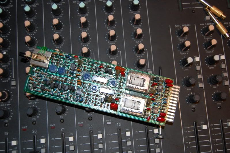
Here are some pictures of it taken apart
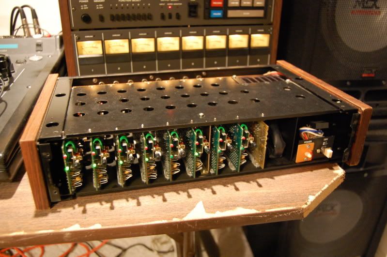
I have it lightly taken apart right now.
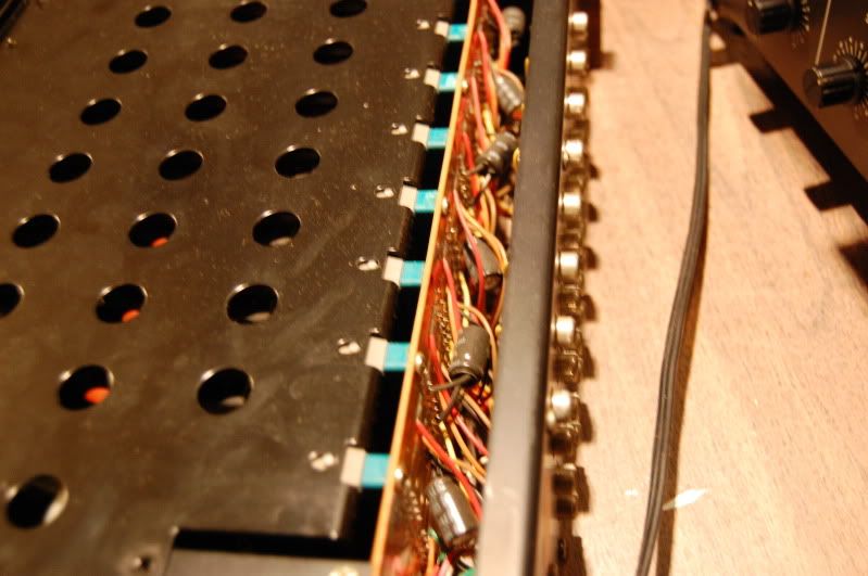
Some of the caps I can see..
I have improvised the one side of the control cable that hooks up to the machine. here are some pictures.
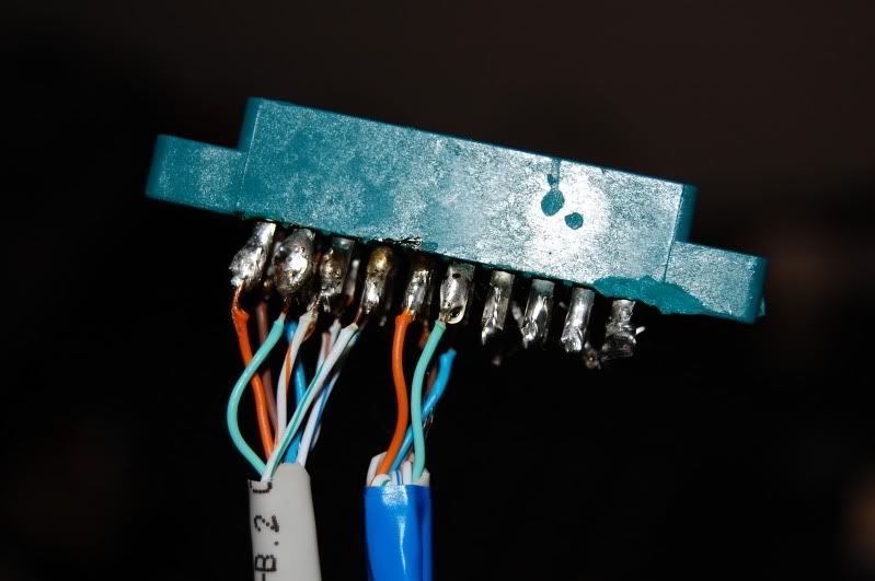
Soldered CAT 5 cable
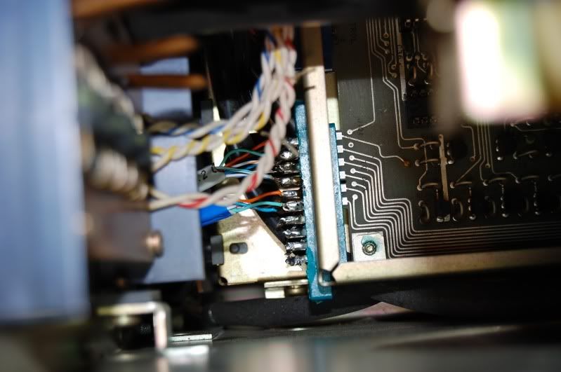
You see some of the contacts are not used and hang off of the side of the actual PCB. but all of the others line up just right. It fits nice and snug on the board.
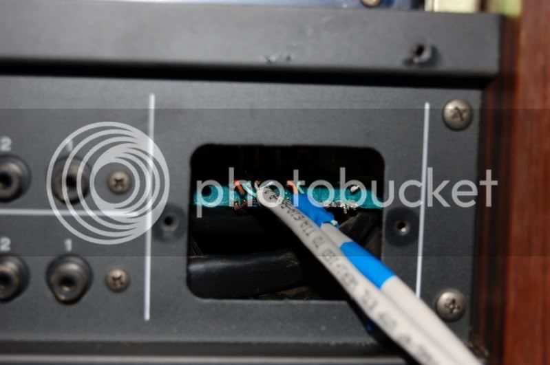
Since the CAT 5 only has 8 conductors I had to use a second one for the last 4 cables and I marker it with blue cable to let me know which set it was. Now.. I think I am going to buy one of those 11 pin circular connectors and hook the other end of my crazy cable to one of those, but for now I would like to test and get used to using the DBX using just the stripped end of the cables stuck into their respective sockets. Anybody think they can help me figure out which cable goes where?") I have the hard copy of the service manual and owners manual for the 80-8 and I have an electronic copy of the DX-8 manual If anybody needs to see something.
I have the hard copy of the service manual and owners manual for the 80-8 and I have an electronic copy of the DX-8 manual If anybody needs to see something.
I have improvised the one side of the control cable that hooks up to the machine. here are some pictures.
Soldered CAT 5 cable
You see some of the contacts are not used and hang off of the side of the actual PCB. but all of the others line up just right. It fits nice and snug on the board.
Since the CAT 5 only has 8 conductors I had to use a second one for the last 4 cables and I marker it with blue cable to let me know which set it was. Now.. I think I am going to buy one of those 11 pin circular connectors and hook the other end of my crazy cable to one of those, but for now I would like to test and get used to using the DBX using just the stripped end of the cables stuck into their respective sockets. Anybody think they can help me figure out which cable goes where? I have the hard copy of the service manual and owners manual for the 80-8 and I have an electronic copy of the DX-8 manual If anybody needs to see something.
Here are some schematic things that look helpful..
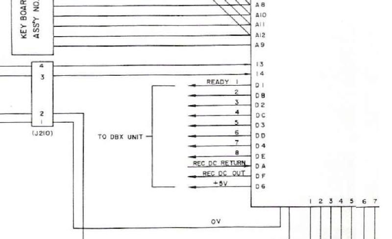
This is what is shown for the connector on the 80-8 PCB. Do you think the numbering pattern on this (D1, DB, D2, DC etc) indicates which is the top and bottom contacts for the socket? I think If I can have this confirmed I may be able to finish hooking this up.
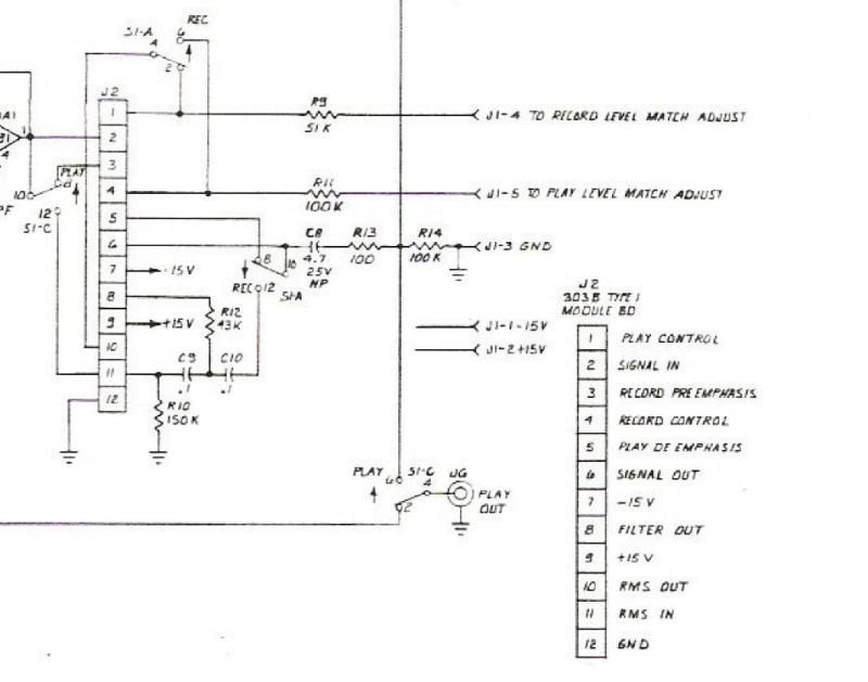
This is what I found on the DX-8 schematics PDF. The manuals do not label these connections the same way. I would assume 1-8 should match up? numbers 10 and 11 on the DBX schematic match up with DA and DF (RMS in and RMS out on the 80-8 schematic? At least from what I have gathered or guessed at.. the 9th connector is the only one in question, because 12 on the DBX one is just a ground and isnt part of that cabling.
I'm totally lost at this point. any help would be greatly appreciated.
Here is a link to a site where the schematic for it can be found for free http://www.audioschematics.com/tascam.html
Here are some pictures of it taken apart
I have it lightly taken apart right now.
Some of the caps I can see..
I have improvised the one side of the control cable that hooks up to the machine. here are some pictures.
Soldered CAT 5 cable
You see some of the contacts are not used and hang off of the side of the actual PCB. but all of the others line up just right. It fits nice and snug on the board.
Since the CAT 5 only has 8 conductors I had to use a second one for the last 4 cables and I marker it with blue cable to let me know which set it was. Now.. I think I am going to buy one of those 11 pin circular connectors and hook the other end of my crazy cable to one of those, but for now I would like to test and get used to using the DBX using just the stripped end of the cables stuck into their respective sockets. Anybody think they can help me figure out which cable goes where?
I have the hard copy of the service manual and owners manual for the 80-8 and I have an electronic copy of the DX-8 manual If anybody needs to see something.I have improvised the one side of the control cable that hooks up to the machine. here are some pictures.
Soldered CAT 5 cable
You see some of the contacts are not used and hang off of the side of the actual PCB. but all of the others line up just right. It fits nice and snug on the board.
Since the CAT 5 only has 8 conductors I had to use a second one for the last 4 cables and I marker it with blue cable to let me know which set it was. Now.. I think I am going to buy one of those 11 pin circular connectors and hook the other end of my crazy cable to one of those, but for now I would like to test and get used to using the DBX using just the stripped end of the cables stuck into their respective sockets. Anybody think they can help me figure out which cable goes where?
I have the hard copy of the service manual and owners manual for the 80-8 and I have an electronic copy of the DX-8 manual If anybody needs to see something.Here are some schematic things that look helpful..
This is what is shown for the connector on the 80-8 PCB. Do you think the numbering pattern on this (D1, DB, D2, DC etc) indicates which is the top and bottom contacts for the socket? I think If I can have this confirmed I may be able to finish hooking this up.
This is what I found on the DX-8 schematics PDF. The manuals do not label these connections the same way. I would assume 1-8 should match up? numbers 10 and 11 on the DBX schematic match up with DA and DF (RMS in and RMS out on the 80-8 schematic? At least from what I have gathered or guessed at.. the 9th connector is the only one in question, because 12 on the DBX one is just a ground and isnt part of that cabling.
I'm totally lost at this point. any help would be greatly appreciated.