TEN81 2009 PROJECTS

GroupDIY Audio Forum

Help Support GroupDIY Audio Forum:

This site may earn a commission from merchant affiliate links, including eBay, Amazon, and others.
EKADEK said:
heres the jpg from my wall with the bass switch stuff.  when the bass shelf/peak switch  is open -  the middle section of caps are what is feeding the wiper of the gain pot back to the amp . when the switch is closed. that cap network is  shorted out. alla a normal shelving style. (im actually not so sure of my explaining/thinking out loud on this point)

http://ekadek.com/wp-content/uploads/2009/06/ekten826.jpg

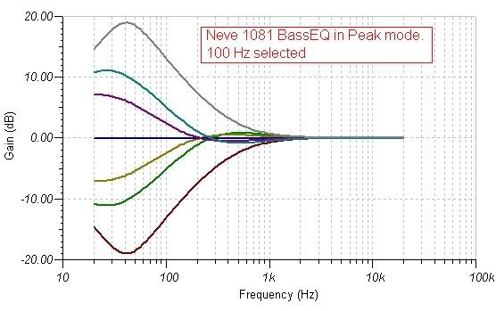
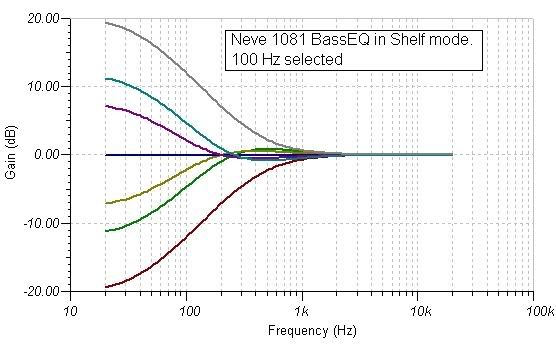
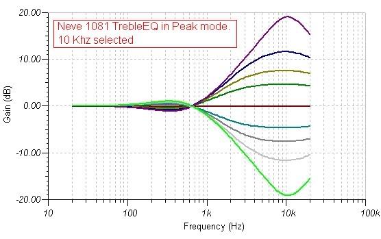
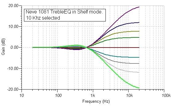
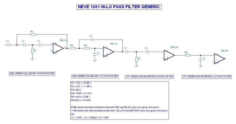
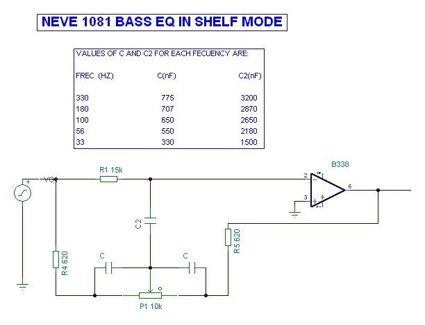
The best way to understand this circuits is to get rid of the variable caps and make a simple drawing for a given frecuency.
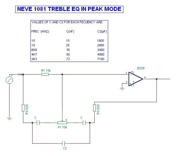
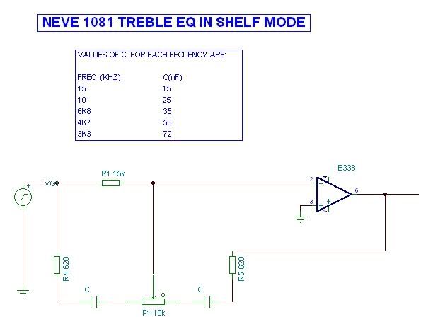
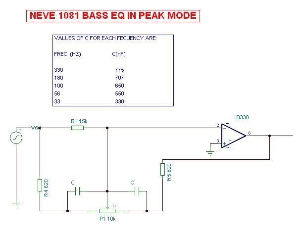
Then you´ll see in shelf mode the middle wafer is not in the circuit, so an usual shelf is obtained. Switching to Peak inserts the middle wafer cap, which acts as a lo pass ( in treble ) or as a hi pass ( in bass ), shapening the shelf into a peak
 
heres a couple of photos from a couple a days ago 69ner. some other closer shots to come.  i apologise for only suppling links. i dont know how else to do it. i try to put actual photos on this page/post. but they dont bloody work . and the instructions dont help me. frustrating.

http://ekadek.com/wp-content/uploads/2009/06/copy-of-img_6718.jpg
http://ekadek.com/wp-content/uploads/2009/06/copy-of-img_6719.jpg
 
Just see how simple it is in fact...

NEVE1081TREBLECIRCUITPEAK.jpg


And the shelving even simpler:

NEVE1081TREBLECIRCUITSHELF.jpg
 
Great new info here and good to see you here Wonderland!!

Ok, here is a link to all the photos that I have taken of an original 1081, hopefully these will be of help.
The zip file is 32mb though but there are many high res pictures of the same module.

www.9voltstudio.se/1081_pics/1081_pics.zip

Here are all the original paperwork that I have, again a very large file but it is the most complete  package I have seen.
Everything seems to be there and these are all high res scans I made myself from an original manual.

www.9voltstudio.se/1081_pics/1081_scans.zip

Not sure how long time I can keep these up since they are taking alot of server space, but a week or two at least, but download them now to be sure to get them.

I am still waiting for my switches and then I want to do the metalwork before I start building mine.
I am doing 16 of these and I have sourced all the original transformers and original Neve plug in amps so they will be as close as possible to original ones.

API


WL thanks for the pictures that helped.

API it showed that it passed through customs hands and I'm sure you should be looking for them real soon :) those tracking numbers do work! Thanks for the files DLoading them now..

Kaz

Just looked at those files, and your correct on the scans. Will have to print those up in the next day or so. Does the input iron connect on a 90 Deg bracket?
 
API said:
Great new info here and good to see you here Wonderland!!


I am still waiting for my switches and then I want to do the metalwork before I start building mine.
I am doing 16 of these and I have sourced all the original transformers and original Neve plug in amps so they will be as close as possible to original ones.

API

Thanks APi!! Still with my ups and downs but basically UP now!!
I may help you with the metalwork issue as I have drawings for it. Also original frontplates in case you need them to copy.
Basically I´m reverse- engineering the whole beast, down to what every single component is doing... and I´m finding great things doing it!!!
Thanks
 
....about rotary switches
(not for the guys want to get unit as the original)
I think the x81 rotary switches "system"
can become a bit more simply and friendly
if a solution as in picture attached
can be applyed (probably less expensive)
on the input gain 1 for mic ,1 for line,
on the eq section where possible for frequency selection
separate from gain +/- controlled by a pot
but a new pcb needed for integration ...
or possible also try as a test by "1000holes card/project board"

any opinion about are wellcome
6T9R
 

Attachments

  • _-X81-EQ-POTS---SIMPLYFICATION---1.jpg
    _-X81-EQ-POTS---SIMPLYFICATION---1.jpg
    34.4 KB · Views: 122
In case you dont mind losing the peak- shelf switches ( which vintech dont  :-\ ), all switching may be done with 1.5 Euro Lorlins. ;D

Just recalculate cap values and off you go!!
 
yes sixtyniner. that 68 pf cap.  i noticed that too when stuffing boards and couldnt find in the original. anyway i decided to not put it on and the stage goes absolutely correct.
maybe that cap was to cure an unstable amp condition. dont know. the stage doesnt need it tho. when it is loaded properly with 100ohm and output transformer the stage goes perfectly. d.c to daylight
thanks wonderland and ap1 for stunning infos and explains . how are u about explaining the filter amplifier network. did u see my extrapolation of EK20049.  
http://ekadek.com/wp-content/uploads/2009/06/ekten817.jpg
http://ekadek.com/wp-content/uploads/2009/06/ekten818.jpg
http://ekadek.com/wp-content/uploads/2009/06/ekten818filta2.jpg

this week im going to make a new b312 circuit drawing . with specific reference to tommytones rev 3 boards.(the ones i have) correct part number co-relations and ALL correct part values.
then maybe a new layout pdf can be made hopefully.
 
EKADEK said:
yes sixtyniner. that 68 pf cap.  i noticed that too when stuffing boards and couldnt find in the original. anyway i decided to not put it on and the stage goes absolutely correct.
maybe that cap was to cure an unstable amp condition. dont know. the stage doesnt need it tho. when it is loaded properly with 100ohm and output transformer the stage goes perfectly. d.c to daylight
thanks wonderland and ap1 for stunning infos and explains . how are u about explaining the filter amplifier network. did u see my extrapolation of EK20049.  
http://ekadek.com/wp-content/uploads/2009/06/ekten817.jpg
http://ekadek.com/wp-content/uploads/2009/06/ekten818.jpg
http://ekadek.com/wp-content/uploads/2009/06/ekten818filta.jpg

There´s a big problem with the drawing of the 1081 to understand the filter, as those 306 amps are in fact dual amps and what it seems to be in and out in the drawings aren´t. I have it handdrawn. Give me 10 minutes and I´ll post a better drawing
 
heavy. im not sure of one  thing tho .
the non - inverting reference. ?? have u missput a couple +- ? i dont quite get it.

 
EKADEK said:
heavy. im not sure of one  thing tho .
the non - inverting reference. ?? have u missput a couple +- ? i dont quite get it.

Obvioulsy backwards. My fault... Notice I titled them right, as non inverting filters ( therefore hanging from + input )
 

Latest posts

Back
Top