


JoshuaUnitt
Active member
Hey folks. I'm working on my first preamp build and wanted to throw some stuff out to the experts here and see what kind of help I could get (doing a search through the forum has been helpful but I wanted to address some specifics). I've got some soldering/build work under my belt but I'm still lacking in the theory department.
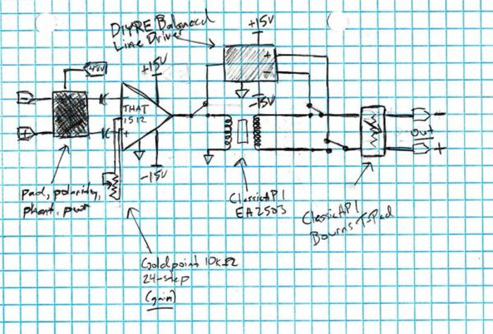
Anywho. here is a quick block diagram I drew up for a THAT1512 pre:
-Of course there are some glaring omissions from the 1512 circuit here, but I wanted to cover the basics. This is what I'm more or less basing the actual circuit off of (from the chip's datasheet):
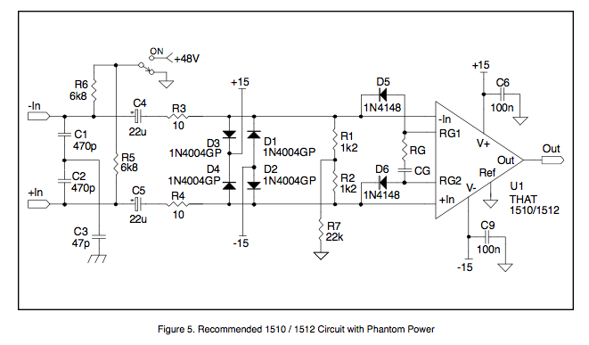
-the "black box" in my block diagram would be comprised of a JLM preamp go-between kit, for simplification purposes. However, I'm not exactly sure where I should add it to the 1512 circuit- should it be after C1-3, where THAT recommends that phantom power should be inserted?
-I plan on using this circuit for phantom power- http://sound.westhost.com/project96.htm any complications?
-As you can see I wanted to have a switchable output balancing stage- active balancing or transformer balancing. Something of a lemon/lime flavor choicefor the end user, I suppose. However I've read that there may or may not be certain things that need to be done with output transformer- adding a single resistor to the secondary, adding a Zobel network to the secondary, etc- but nothing definitive. And as far as Zobel networks go, the only information I have seen for calculating the values relates directly to when the next stage is a speaker- not a +4 line input. Any help here?
-finally, the T-pad 600ohm attenuator, which I figured would be a good way to help drive the pre into that fabled land of saturation and analog happiness. reasonable estimation? (I'm gonna assume in advance that it's not that simple)
Thanks in advance for any and all help, it's appreciated!
Peace,
Josh
Anywho. here is a quick block diagram I drew up for a THAT1512 pre:
-Of course there are some glaring omissions from the 1512 circuit here, but I wanted to cover the basics. This is what I'm more or less basing the actual circuit off of (from the chip's datasheet):
-the "black box" in my block diagram would be comprised of a JLM preamp go-between kit, for simplification purposes. However, I'm not exactly sure where I should add it to the 1512 circuit- should it be after C1-3, where THAT recommends that phantom power should be inserted?
-I plan on using this circuit for phantom power- http://sound.westhost.com/project96.htm any complications?
-As you can see I wanted to have a switchable output balancing stage- active balancing or transformer balancing. Something of a lemon/lime flavor choicefor the end user, I suppose. However I've read that there may or may not be certain things that need to be done with output transformer- adding a single resistor to the secondary, adding a Zobel network to the secondary, etc- but nothing definitive. And as far as Zobel networks go, the only information I have seen for calculating the values relates directly to when the next stage is a speaker- not a +4 line input. Any help here?
-finally, the T-pad 600ohm attenuator, which I figured would be a good way to help drive the pre into that fabled land of saturation and analog happiness. reasonable estimation? (I'm gonna assume in advance that it's not that simple)
Thanks in advance for any and all help, it's appreciated!
Peace,
Josh


![Soldering Iron Kit, 120W LED Digital Advanced Solder Iron Soldering Gun kit, 110V Welding Tools, Smart Temperature Control [356℉-932℉], Extra 5pcs Tips, Auto Sleep, Temp Calibration, Orange](https://m.media-amazon.com/images/I/51sFKu9SdeL._SL500_.jpg)


")