the Poor Man 660 support thread

GroupDIY Audio Forum

Help Support GroupDIY Audio Forum:

This site may earn a commission from merchant affiliate links, including eBay, Amazon, and others.
rrs said:
I have replaced all the Q1,2,3 transistors but due to the solder pads peeling off so easily this section is virtually all point to point now. I am sure though I have copies all the traces from both top and bottom of the board.

It's a art to remove stuff a few times from the pcbs that are made today. Low heat and careful, it's best to not bend up the leads and then solder it makes getting things out a simpler task.
 
Don't try to break  or snap the solder before it is warm enough
[ what i learn every so often ] if it doesn't come easily  , warm it again

and everybody , get out your Leslie for the Ringo Star version  " it don't come easy "
 
rrs said:
I have replaced all the Q1,2,3 transistors but due to the solder pads peeling off so easily this section is virtually all point to point now. I am sure though I have copies all the traces from both top and bottom of the board.

I had the same experience. The boards just aren't repair friendly, and sometimes even the vias come off. Q1,2,3 burned themselves for no reason and I ended up p2p for that section eventually. It works now, but I have to keep my fingers crossed.

This high voltage regulator design is also perhaps slightly "too clever" (at least in parts count) for a simple and dumb brute force beast like a vari-mu compressor.
 
OK replaced (Q4) IRF820 with IRF840 and all seems good on the PSU side.

BUT the problem seems to be when I attach eitheror both of the channel PCB's that the voltage drops once it gets around 110V along with an ominous faint crackling sound coming from the PSU area.

Advice would be greatly appreciated.

Also could this be the tubes? Will it be safe to test without the tubes in?
 
rrs said:
BUT the problem seems to be when I attach eitheror both of the channel PCB's that the voltage drops once it gets around 110V along with an ominous faint crackling sound coming from the PSU area.

Are you sure your transformer is OK?  Can you isolate where the noise is coming from?

Cheers,
---
Don
 
Actually it's kinda more a sizzling noise.
Not 100% sure about the transformer but the noise does seem to be coming fro that area. Is there any way to prove the transformer is faulty?

I am still getting 401V before the rectifier. If anything it could be coming from the caps around C1,2 also, very hard to pin down.
 
rrs

i am having the same problem but  after the rectifier ,  seeing over  400vdc @  R1 and the gate of  q4.


tx output blk blk  290 acv
 
OK the crackling seems to be fixed after changing C1,2.

Voltage still dropping under load (same with both channels) after around 110-120V or 5-6 seconds. Can anyone recommend a way to isolate this problem.
 
I wonder if 400V is normal before the regulator (Q4). I have these voltages even when the unit was working. Considering C1,2 needed to be replaced on mine I got a higher voltage cap instead of the 400V recommended.

The IRF840 seems to be handle 500V if I read correctly so shouldn't be an issue there. http://australia.rs-online.com/web/search/searchBrowseAction.html?method=getProduct&R=5410036

Since finding these caps blown I am hoping that trying another regulator may improve things.

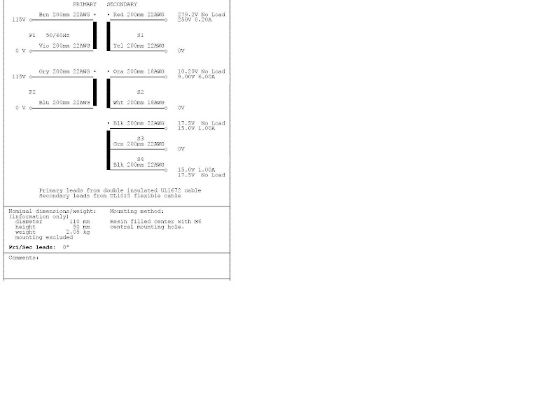
This is the transformer I am using (Avril Lindberg)and we in Australia have 240V so primary's are wired accordingly.
avellindberg.JPG


I have
Yellow ...pin 1 250V
Red ......pin 2 250V
Black ....pin 3 AC
Green ...pin 4 GND
Black ....pin 5 AC
Violet and grey tied together.
Orange and white to the rectifier.
 
rrs said:
I wonder if 400V is normal before the regulator (Q4). I have these voltages even when the unit was working. Considering C1,2 needed to be replaced on mine I got a higher voltage cap instead of the 400V recommended.

The IRF840 seems to be handle 500V if I read correctly so shouldn't be an issue there. http://australia.rs-online.com/web/search/searchBrowseAction.html?method=getProduct&R=5410036

Since finding these caps blown I am hoping that trying another regulator may improve things.

This is the transformer I am using (Avril Lindberg)and we in Australia have 240V so primary's are wired accordingly.
avellindberg.JPG


I have
Yellow ...pin 1 250V
Red ......pin 2 250V
Black ....pin 3 AC
Green ...pin 4 GND
Black ....pin 5 AC
Violet and grey tied together.
Orange and white to the rectifier.

When your saying you have 250V on Yellow pin 1 in reference to what?

If you look at what is listed in your sheet 250V is from Yellow to Red on S1, it should not be 400 or 500... that should clearly indicate something is wrong.

Take a handfull of wire nuts and isolate the lose secondary wire ends of your transformer so you don't hurt yourself. Plug in the primary side and test each set of secondaries according to you sheet.

Lastly are you sure it's not the blue and gray tied together?
 
Hi Kazper and thanks for the reply.

I have 240V mains power here so have hooked up Toroid in series. So to confirm Grey and violet are tied together on the primarys.

Voltages between Red and Yellow are 294 (no load) a little over 279.2 but was told previously the higher voltages may be due to being 240V mains.
Voltages between both Black and green are 15V.

So I am assuming this looks good from the transformer side of things. If so can anyone shed some light on why I and others here may be getting up to 400V up the the regulator. And is this ok.

[Edit] Reading back through this thread I see this problem not to be uncommon. Moby has suggested the Mains Transformer could be the culprit. As I am still seeing around 400V before the Q4 rectifier even after the voltage drop I assume this may not be my problem and hoping I may get lucky with another IRF840 like elektrovolt. Still worried about the 400V though.

 
mitsos said:
My heaters are only 3V! So there's the obvious problem. The trafo I am using is only 6VAC or so, (I'm getting 8.7VDC with no load after rectification) so I'm gonna pull out the 2R 50W .....

The other thing is that the 245V and 136V, which were just fine a minute ago (since then I powered down, bled caps, and powered up but forgot to remove my bleeder resistor (47K I think) from my DMM (I had them connected together so I could watch the voltage dropping)  so when I went to measure voltages with the unit on again, I measured with the bleeder resistor in parallel to my DMM. I'm not sure if this might have blown up the second IRF (I hope not) but I am now getting less than 13V instead of 245 and 4 instead of 136. I'm guessing Q5 is done, because I'm getting 13V on the cathode side of D9 (protection diode for Q5?) and 4V on the anode side.
OK, so I tried a 0.92R resistor in place of the 2R and it still drops my heater to 4.2 or so (should have written it down). My pre-resistor voltage is 6.25V, so can I just omit the huge resistor?

Also, about my high voltage, I swapped in 2x IRF840s and still had the same power issue, which I traced to an open-circuit R8, so I guess my little fumble with the bleeder resistor (47K to ground right after R8) is what killed it.  Gonna see if I can get another 2W tomorrow and hook it up again.  As it is, I am getting 390V or so pre-Q4 and 254V post Q4 but very little V around Q5.

getting closer...
cheers!
 
Hi David,

as posted beforehand, I've exactly the same issues on my psu board. Changed every Q1 - Q5 (although I see no burning marks on any component) all the components test fine, and without load I'm getting perfectly fine voltages. I'm working on this issue since the last couple of days without any luck :(

cheers,
christoph
 
Seems like this PSU is a tricky beast. Shame the designer never helps out here and is left to the same few. Maybe more could help out if there was a freely available schematic.

Anyway

This voltage drop issue I am having seems quite a common issue reading back through posts and may be centered around Q4. Some seem to have tried a bunch of IRF840 and got lucky with one or maybe some insulated them better second, third or fourth time around. I have just brought another 840 so will see soon.

Another thought is how common this issue is considering the amount of Poormen built that post here. 21 built units reported here and at least 5 with this issue going through the thread which is 25%. Maybe instead of us crossing our fingers there maybe some thought to modify the PSU to be more suited to this project.

I know Moby has consistently questioned the power Transformers but no one seems to have one proven faulty yet.
 
In all fairness, you just pay a small price for the PCB. You don't pay anything for a support contract to get it built and that is part of the risk you take doing DIY. Yes it's helpful when they chime in but it's never a expectation. I understand the left out in the whim feeling from other projects.

There is other ways to get the power requirements for this project and bypass the PCB design that was provided. That though is something you would have to design or look into to making it a reality.

 
kazper said:
In all fairness, you just pay a small price for the PCB. You don't pay anything for a support contract to get it built and that is part of the risk you take doing DIY. Yes it's helpful when they chime in but it's never a expectation. I understand the left out in the whim feeling from other projects.

I do understand the risks involved and am appreciative of the efforts of may here who share there knowledge and time. My point was that whilst Analag holds the schematic secret it makes this pretty much a closed community project. It would help greatly if more people were involved to make this a more successful build for the whole community here.

Whilst we don't expect to have our hands held every step of the way there is always a moral (and sometimes legal)obligation for something that is paid for, may cause serious injury, or may be misleading in how the project is presented.

As Analag does have time to post here now and again It would be helpful if those posts could help enlighten us instead of being in a defensive or mocking tone.
 
Did Analag design the PSU?  I thought it was Volker or somebody... ?

Anyway, I think exploring other PSU designs and options would be a good idea. 
 
tommypiper said:
exploring other PSU designs and options

The PSU design here I adapted from a vari-mu project by rotheu. In fact I will be using it for big-*** vari-mu project in the future as well. I made it a bit safer and more generic for all-around use. I'll do a PCB sometime as well.

http://www.groupdiy.com/index.php?topic=41509.0

For vari-mu you obviously don't need the zener bypass switch (it's a feature for distortion for a preamp use only).

The original PSU on my poorman works fine by the way, but I do think it's overly complex for the job, considering the simplistic amps it's used for, or the trouble shooting skills required if it ill-behaves. Also, it has been said before, but all the group buy PSU transformers this far for poorman were insufficiently rated.
 

Latest posts

Back
Top