tl-audio m3 tubetracker dismantling

GroupDIY Audio Forum

Help Support GroupDIY Audio Forum:

This site may earn a commission from merchant affiliate links, including eBay, Amazon, and others.

1954U1

Well-known member
Joined
May 19, 2008
Messages
468
Location
Italy
I've a used TL Audio M3, and all the trimmers for calibration, on the back, were gone out of the holes, maybe because in the years the PCBs have gone a little bent.
So, the only solution [and also for doing the "balance" calibration, only doable with the M3 opened] was to dismantle it.
I'm posting here the photos, because the only way to reassemble the damn thing is to make a little mod, so I'm documenting it.


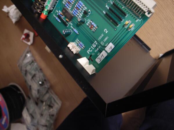
Here, the 2 visible screws and bolts, like all the others, needs to be removed and no more used [the ground's bolt too]:
0.jpg


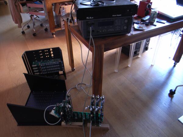
Rearranging the channels for doing the balance calibration:
1.jpg


Pieces of white rubber glued to the metal semi-chassis, against each channel board, for re-align the PCBs and thus the trimmers on the back holes:
2.jpg


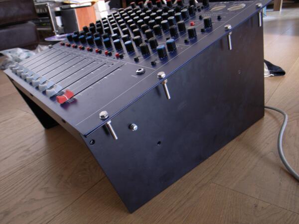
New bolts and screws on the rack mounting holes [they replace the impossible-to-use internal ones].
And ground screw in a new made hole.
3.jpg
 
MartyMart said:
Why was it impossible to get the side panels with screws back on ?
I'm sure it wasn"t designed to have that feature !!

Marty.

Its nearly impossible, because the U shaped piece of metal in which are the channels PCBs, fastened with the plastic bolts of the jacks and the screws of the XLR receptacles,
do _completely_ cover the accessibility of the bolts viewable in 1st pic.
And you cant just have the side-panels already attached to front panel with these bolts, and then place the rear panel with channels PCBs, because you do not have room for inserting the PSU connector on the bus board, neither the ground cable.
In fact, to dismantle the M3, with this absurd system, you have to bend and pull, exactly because these bolts arent accessible.
To reassemble things, it makes lot more sense to have first all the channels boards fastened to the "U" semi-chassis, then insert the PSU connector on the bus board and fasten the ground screw, and finally fasten the rear panel to front panel and side panels, still not secured each to other.

Its a lot more simple to see than to explain.. I've dismantled and reassembled lot of gear, never had difficulties like these with the M3.
This thing was for sure at least poorly mechanical designed.. see the out-of-axis trimmers issue.

 
pucho812 said:
what model of ap is that one?

Portable One Plus.
Great machine, I've bought it from a member here.

I'm just writing a script for to have the AP printer output connected to a linux laptop, having as result hi-res graphic files with the freq-noise-level responses.
I've had to buy for that a B&B serial/parallel converter.
 
Can you snap some better pics of a channel strip/master section?
For gearporn junkies?
::)
 
jackies said:
Can you snap some better pics of a channel strip/master section?
For gearporn junkies?
::)

Sorry its closed now|  :(
I was so angry with the M3 that I didnt make my usual verbose photo archive of all the bits inside..
gone really near to throw the mixer out of the window or destroy it with a hammer..
Anyway now I'm glad to have it calibrated.. it has a place, at the end.
[but forgot about the mic pres, they're dull and super-scratchy on gain knobs].

Here are the only "interesting" pics, linked to hi-res, I've made
[the hi-res are 3264x2448, so maybe its better to save the file rather than viewing it in browser, if you want to see all the details]:

busses&valves PCB:
000

M3 on wood:
111

channel strip:
222

master board:
333

trimpots re-aligned!
444


Hi and thanks for posting pictures!
Unfortunately, I can't see them, something went wrong with links or something?
???
 
WOW! cool thread. I bought one of these about 6 months ago for 1000.00 with channel 6 out. it would up being a bad trace on one of the tlo72 opamps. cool sounding little board and the eq is awsome sounding aswell. mine also has the calibration thingee, however i calibated it with a very small screwdriver. Arty 
 
I know this is an extremely old thread but it was the only thing I could find when searching for information about how to dismantle the tubetracker m3.  I thought I'd write a post with my experiences as I've just swapped the valves in my m3 and it was a nightmare for exactly the reasons posted above by 1954U1.  If you're changing the valves the key is to only take the back of the mixer off - don't unscrew anything from the blue front panel.  Otherwise you'll get yourself into a whole world of pain like I did.  The steps are:

1. if it's in the wooden housing unscrew the 8 screws and lift the mixer out.
2. turn the mixer over and place on something soft so the front panel doesn't get damaged (the full weight will be on all the pots but I couldn't find any other way of supporting it!)
3. unscrew the housing around the grey power cable where it enters the mixer - move this further down the cable out of the way
4. unscrew the 3 screws on the front of the mixer just above the black grill, and also the ones at the back
5. unscrew the 4 screws on the sides of the mixer
6. unscrew all of screws on the xlr ins/outs and the housings of the jacks
7. lift the panel up and once it's clear of the jacks/xlrs/buttons, tilt it so that the end with the power input is lower than the opposite side
8. as you lift it up, the poor design of the unit means you're going to have to apply some force to (non permanently) bend the side of the mixer out
9. the back of the mixer should come off and you'll see the 5 valves

If you're just changing the valves, don't be tempted to take the front of the mixer off like I did - all the LEDs are housed in tiny holes that are really difficult to get re-aligned.  If you need to do anything more complex like replacing components I would still take the back off the mixer and then remove each card individually to test.  The way to do this would be:

1. remove the back of the mixer as above
2. stand mixer vertically with the fader strips nearest the floor.
3. on the offending channel, undo the screw just below the gain pot, and the screw above the mute/pfl swiches
4  important: do not undo the screws at the top or bottom of the fader strip otherwise you will be unscrewing the main card holding the fader strip/valves
5 once you've removed the pots then you should be able to lift the card out from the other side

I guess if you were doing balance calibration like 1954U1 did (I guess using the trim controls on the cards themselves (not accessible without taking the cards out one by one), you could take all the cards out and start at one end and work with each channel at at time.  I still would avoid taking the front panel off at absolutely all costs as getting the LEDs to line back up with the holes without bending them and messing around/potentially damaging them is extremely hard and as 1954U1 said, you will end up sacrificing the bolts pictured in his first photo if you take the sides off.  It's impossible to explain why without quite a complex diagram, but the point I want to make is just take the back off the mixer unless you want to enter a world of pain!

I hope one day someone sees this post before they tackle the m3!  I really love the mixer and have enjoyed making countless recordings using it, but opening it up is tricky because of the poor mechanical design.

Good luck.

Owain
 
I know this is an extremely old thread but it was the only thing I could find when searching for information about how to dismantle the tubetracker m3. I thought I'd write a post with my experiences as I've just swapped the valves in my m3 and it was a nightmare for exactly the reasons posted above by 1954U1. If you're changing the valves the key is to only take the back of the mixer off - don't unscrew anything from the blue front panel. Otherwise you'll get yourself into a whole world of pain like I did. The steps are:

1. if it's in the wooden housing unscrew the 8 screws and lift the mixer out.
2. turn the mixer over and place on something soft so the front panel doesn't get damaged (the full weight will be on all the pots but I couldn't find any other way of supporting it!)
3. unscrew the housing around the grey power cable where it enters the mixer - move this further down the cable out of the way
4. unscrew the 3 screws on the front of the mixer just above the black grill, and also the ones at the back
5. unscrew the 4 screws on the sides of the mixer
6. unscrew all of screws on the xlr ins/outs and the housings of the jacks
7. lift the panel up and once it's clear of the jacks/xlrs/buttons, tilt it so that the end with the power input is lower than the opposite side
8. as you lift it up, the poor design of the unit means you're going to have to apply some force to (non permanently) bend the side of the mixer out
9. the back of the mixer should come off and you'll see the 5 valves

If you're just changing the valves, don't be tempted to take the front of the mixer off like I did - all the LEDs are housed in tiny holes that are really difficult to get re-aligned. If you need to do anything more complex like replacing components I would still take the back off the mixer and then remove each card individually to test. The way to do this would be:

1. remove the back of the mixer as above
2. stand mixer vertically with the fader strips nearest the floor.
3. on the offending channel, undo the screw just below the gain pot, and the screw above the mute/pfl swiches
4 important: do not undo the screws at the top or bottom of the fader strip otherwise you will be unscrewing the main card holding the fader strip/valves
5 once you've removed the pots then you should be able to lift the card out from the other side

I guess if you were doing balance calibration like 1954U1 did (I guess using the trim controls on the cards themselves (not accessible without taking the cards out one by one), you could take all the cards out and start at one end and work with each channel at at time. I still would avoid taking the front panel off at absolutely all costs as getting the LEDs to line back up with the holes without bending them and messing around/potentially damaging them is extremely hard and as 1954U1 said, you will end up sacrificing the bolts pictured in his first photo if you take the sides off. It's impossible to explain why without quite a complex diagram, but the point I want to make is just take the back off the mixer unless you want to enter a world of pain!

I hope one day someone sees this post before they tackle the m3! I really love the mixer and have enjoyed making countless recordings using it, but opening it up is tricky because of the poor mechanical design.

Good luck.

Owain
Quick comment on this post - excellent documentation Owain. I was just about to crack my newly acquired M3 apart and read this detailed instruction - thank god. It's not quite as bad a job to get this open as described, mostly just tedious having to remove all the XLR screws and TRS nuts on the 'back' panel. And the 'bending' of the panel is only slight so as to release the 'back' panel from the sides. Although it was probably painful having not had the benefit of these great instructions.

Unfortunately I tried to remove a few pot caps and in doing so they seem to have lost their 'detent'. I'm not sure how this happened. And as a consequence I am glad that I don't have to remove channel strips.

All this just to blast this thing with Deoxit - seems all the years of non-use and dust had taken a toll...

Ben
Made a video of this for posterity...
 
Just found the schematics and calibration routine on Wayback Machine
 

Attachments

  • TL Audio M3_Schematics.pdf
    1.6 MB
  • TL Audio M3_Calibration.pdf
    133.1 KB
i'm in need of a Gain Potmeter for the M3 - Alpha RV16, dual, one layer 05C5K (rev. log), one layer B10K, is someone aware who could have them in stock?
 

Latest posts

Back
Top