Transformer Rewind - learning the first steps

GroupDIY Audio Forum

Help Support GroupDIY Audio Forum:

This site may earn a commission from merchant affiliate links, including eBay, Amazon, and others.

Whoops

Well-known member
GDIY Supporter
Joined
May 9, 2008
Messages
8,424
Location
Portugal
Hi,
I would like to start learning the basics on simple transformers winding/rewinding.

I've ordered a hand coil winding machine with counter from HK, just waiting for it to be clear in the customs.
this is the unit:

https://www.ebay.co.uk/itm/NZ-1-Manual-Hand-Dualpurpose-Coil-Counting-and-Winding-Machine-Winder-coiler/391892039419?hash=item5b3e95f6fb:g:MR0AAOSw10NZw2Sz

As a first project I would like to rewind a small 110V(primary)  transformer to a 240V primary.
It's an EI small transfrmer that I need for a project

I hand wounded the coils and counted the turns of this transformer.

Each secondary has 260 turns and I measured the thickness of the wire , 0.3mm , so it should be 29gauge wire

The primary has 2066 turns with 0.1mm wire, 38 gauge

The Bobin hole is 13mx13mm
Ans the EI lams are stacked 2x2

I would like to ask how do I calculate the number of turns needed for the primary for 240V 50hz operatition?

Is that as simple as doubling the number turns?

Thank you so much


Well, since transformers work by ratios, the short answer is "yes".

http://sound.whsites.net/xfmr.htm (and subsequently parts 2, 3 and 4)

Part 4 is a bit of a TL;DR though - http://sound.whsites.net/articles/xfmr4.htm
 
I'm quite sure that only matters if 1) you're running out of space on the bobbin / in the winding-window, and/or 2) you're trying to minimize costs (re: copper).
 
How about the transformer being made for 60hz (at 110v) and using it for 50hz (240v)?

what considerations should I have in the rewind?
How could that affect the number of turns?
 
maybe start with something less dangerous than 220 line voltage,

60 Hz / 50 Hz = 1.2

so you need 1.2 times as many turns to keep the flux the same.


CJ said:
maybe start with something less dangerous than 220 line voltage,

60 Hz / 50 Hz = 1.2

so you need 1.2 times as many turns to keep the flux the same.

Hi CJ,
thank you

It's what I have on my bench at the moment.

It's a really small and simple transformer (basic layers) so I thought it would be good as a first project.
I'll be shure to be use the right amount of insulation and testing procedures.

I will measure it for shorts before powering it up, and I will power it the first time connected to a Light Buld current limiter.
If there's any more safety procedures I should do please let me know.

so to calculate the aproximate turns calculation for the primary in this case will be
110V (60hz) to 220V (50hz)

2060 x 1.2 x 2 = 4958 turns

is that correct?
 
CJ said:
seems high for a pwr line primary,

is that 50 EI?

Yes it's also seems quite high for me
I think my EI lams are smaller than 50 EI

using the attached document my lams are
A= 33.4
B= 41
U=6.4

So it seems to be EI-41T or EI-41(2H)
 

Attachments

  • 112825454_EI%20LIST.jpg
    112825454_EI%20LIST.jpg
    133.6 KB
> Shouldn't the wire thickness be half of what was installed for 110v?

The *area*, not thickness. Should be 0.707 times the diameter.

And as CJ says, a transformer marginal for 60Hz should be re-proportioned for 50Hz. Hard-fact, it should be bigger for the same VA output. In practice, you may get away with fudging the turns and not expecting "all" power at full voltage and safe temperature.
 
what is the voltage and current of the secondary winding, is it center tapped or just two wires,

what kind of supply, plus/minus  or single? voltage regs used or not?

we need all the specs before designing,
 
CJ said:
what is the voltage and current of the secondary winding, is it center tapped or just two wires,

what kind of supply, plus/minus  or single? voltage regs used or not?

we need all the specs before designing,

Secondary is Center tapped

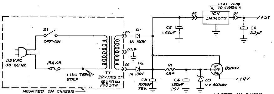
The schematic says it's a 20Vac 250ma secondary

a5bu1gQ.png


The rails are +5V (7805 style regulator) and +12V (discreet regulator),
So I don't even think the AC voltage output of the transformer needs to be that high.
15V on the secondary should be plenty to be rectified for the circuit needs

thanks

attached the full schematic of the unit


Attachments

  • DOC010418-01042018114203.pdf
    38.9 KB
change that circuit to bridge rect and you save 20% power due to non interupted sec current,

and you save hassling 1 lead breakout,

primary flux

4000 T = 17 KG
4500 = 15 KG
5000 = 13.6
5500 =  12 KG

15 volts plus 2 volt rect drop = 17 V-ac

220/17=12.84 turns ratio,  maybe a 2% bump for efficiency correction,

pri current  250 ma /12.84 = 19.4 ma  so #37

sec wire # 26 

try 4000 T / 12.84 =  311 turns for the sec,

gonna be a tight fit,  maybe 28 for the sec wire,
 
McLyman  approach - area product, watch out, he uses Teslas, probably a closet commie,  :D

Apparent Power  Pt=P in + P o

P in = P o / n  where n  is xfmr eficiency  some algebra>

Pt = P o / n  + P o

Pt = P o ( 1 / n + 1 )

Pt = I o x (E o + V d ) x ( 1 / n

Pt = .250 x (15 + 2) x (1/0.95 +1)

Pt = .250 x 17 x  2.0526 = 8.72              now Area Product (wind window area x core x section)

Ap= (Pt x 10^4 / K Bm f Ku Kj)^1.16   

K=4.44 for sine wave  Bm= 1.2 Tesla f = Hz  Ku = .4 (what % copper in window)
Kj = 366 (current density for 25 Degrees C operation)

Ap= (8.72 x 10^4 / 4.44 x 1.2 x 50  x 0.4 x 366)^1.16

Ap = 2.23^1.16 = 2.543

pick core from chart:  looks like 21 EI which has a 0.5 tongue  or 13 mm we have a match.


Attachments

  • core.JPG
    core.JPG
    193.7 KB
what about regulation?

we have 17 V-ac @ 250 ma , 50 Hz sine wave, lets design for 5% regulation

1. Calculate power output:  Po=VA  = 17 x .250 = 4.25

2. Calculate electrical conditions:

Ke = 0.145 K^2 f^2 Bm^2 x 10^-4

K=4.44 (sine wave)  f = 50 Hz  Bm = 1.2 T

Ke = 0.145 x 4.44^2 x 50^2 x 1.2^2  x 10^-4

Ke = 1.03

3. Calculate the core geometry

Kg = VA / Ke x Reg

Kg = 4.25 / 1.03 x 5

Kg = 4.25 / 5.15 = 0.825

4. Select core from chart: (to use chart multiply 0.825 x 1000 = 825

Looks like we need a bigger core for 5% regulation, about a 68 EI (between 75 and 87

but we have regulators so no big,

what will our regulation be with your core?

rearrange formula Kg = 4.25 / 1.03 x %  > % = 4.25 / 1.03 x Kg

your core is actually a bit bigger than 50 EI, more like 21 EI which has a Kg of 181.

divide 181 by 1000  for our formula  = .181

% reg = 4.25 / 1.03 x .181 = 4.25 / 0.1864 = 22.8 %

not too good, better add a few more volts to the secondary, you can decrease pri turns or add sec turns,

this design is right on the edge, a 625 EI core sure would be nice, unless you are not going to be drawing the full 250 ma.


Attachments

  • Kg.JPG
    Kg.JPG
    215.7 KB
every book has their own take on transformer design, some are bare bones and some get really involved, the reason for the more involved way being the savings of cost and material, and space.

here is an easy way to pick the core size, just compute VA which is about  4 to 5 with this design, and read the core size off the chart,  this chart says we need a 625 EI , note that the spec is for 60 Hz so we need to derate, 
 

Attachments

  • VA vs Core.JPG
    VA vs Core.JPG
    205.1 KB
this is how they did it back in 1947, back when engineers would rather spend their time on the important things in life, like smoking Lucky Strike non filters and flirting with the gal at the typewriter, why waste time with a slide rule when you can design a pwr xfmr in 3 seconds like this>

pick the VA rating and find the core #, core #1 in this case

go to the graph, find your pri and sec volts, chart up to the turns and read your primary and secondary turns, tell the boss your done and back to the secretary.

notice how regulation gets worse with the smaller cores,
 

Attachments

  • Reuben Lee.jpg
    Reuben Lee.jpg
    374 KB
Hi CJ,
Thanks you so much for all your help and all the information, I realized how much I'm learning just in a few days, thank you

I rewound the transformer, it was a really tight fit, wire is on the limit of the bobin, but it fit.
I used quite a lot insulation between Primary and secondary and between all the coils ends.

I measured DC res:

Primary: 539ohms
Secondary: 5.9 ohm

The problem is when I measure resistance between Primary and Secondary my DMM measures 1Megas then the measurement keeps falling until 0.6 Megas

Not Good News I suppose!!!!


Back
Top