Hey Everyone,
I'm working on this Midland Automatic Level Controller right now and could use some hive brain help. I can't find much of anything about these online. It's a pretty obvious rip off of the level loc, judging by the 6"/12"/18" distance markings on one of the pots and the look of the unit in general, however it doesn't follow the Level Loc schematic very closely.
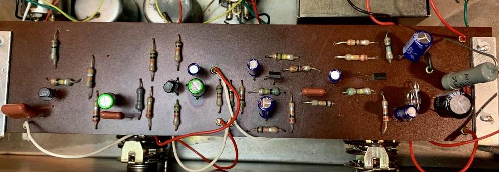
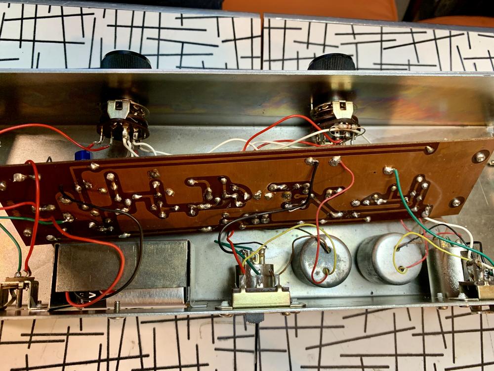
Here are some photos: https://imgur.com/a/CHrVVL0
Problem: Unit passes signal in bypass but drops signal ~20dB when compressor is engaged and I don't hear any compression happening. I've completely recapped it and it is passing a little more signal now, but still not working correctly.
Similarly to the Level Lec, the bypass switch powers down the entire circuit and it becomes entirely passive, going through the input & output transformers. Unlike the Level Loc, the unit doesn't have an aux out, only xlr in & out, nor does it have an input pot.
I'm getting some interesting measurements that I wanted to share because I'm not exactly sure if what I'm finding is normal or not: When I send a 2v sine wave to the unit with the compression circuit engaged, I get 1v on the secondary of the input transformer. Once I switch the unit to bypass the secondary jumps up to 40v. I'm not sure if this is normal behavior and I'm curious if any of you can help to enlighten me. I understand that it might change given the load of the circuit, but this seems pretty drastic to me.
Additionally, when the unit is engaged, I'm measuring .01v on the output of the first capacitor (.1uF) in the circuit and it stays at the voltage all the way through the circuit. The cap is brand new and tested properly, but this seems like a big drop to me.
There are two transistors in the audio path that are both giving different readings on each of their legs. I switched these and they have the same readings each one was giving before at it's respective place in the circuit, so I don't think either one is bad. They also both tested out to be ok when I pulled them out of the circuit.
Any help would be much appreciated and apologies in advance for my ignorance - I'm certainly not anywhere near where I'd like to be with this type of work.
Cheers,
Erik


![Electronics Soldering Iron Kit, [Upgraded] Soldering Iron 110V 90W LCD Digital Portable Soldering Kit 180-480℃(356-896℉), Welding Tool with ON/OFF Switch, Auto-sleep, Thermostatic Design](https://m.media-amazon.com/images/I/41gRDnlyfJS._SL500_.jpg)

