tube mic pre re-purposing; upgrade filament regulator?

GroupDIY Audio Forum

Help Support GroupDIY Audio Forum:

This site may earn a commission from merchant affiliate links, including eBay, Amazon, and others.

emrr

Well-known member
Joined
Apr 12, 2006
Messages
8,659
Location
NC, USA
Standard Chinese tube mic power supply, with a 1A rated LM7806 that has a heatsink on the 6V filament supply.  These seem to be used with 300mA filament tube mics.

I'm putting it in service with 600mA filaments, and am wondering if it's advisable upgrading to a 1.5A rated L7806.    Is constant current at 60% rating going to cook this thing over time?  I know, it's down to the heatsink, and no idea how I'd assess that outside of prolonged heat testing. 

The existing regulator seems to do the job fine in medium duration testing, but I've not let it burn all day in a tracking session.  The power transformer isn’t showing any decreased output from the load.

10 minutes in, I can't touch the heatsink.  Probe I have is too big, it's leveling out at 120F, it's definitely hotter than that. 
 
I would use the higher rated regulator and have mounted them on a larger heat sink via flying leads on the case. Thats in the larger Chinese power supply.
I have had the power transformers cook, standard heater current. So something to consider.
 
EmRR said:
Standard Chinese tube mic power supply, with a 1A rated LM7806 that has a heatsink on the 6V filament supply.  These seem to be used with 300mA filament tube mics.

I'm putting it in service with 600mA filaments, and am wondering if it's advisable upgrading to a 1.5A rated L7806.    Is constant current at 60% rating going to cook this thing over time?  I know, it's down to the heatsink, and no idea how I'd assess that outside of prolonged heat testing. 

The existing regulator seems to do the job fine in medium duration testing, but I've not let it burn all day in a tracking session.  The power transformer isn’t showing any decreased output from the load.

10 minutes in, I can't touch the heatsink.  Probe I have is too big, it's leveling out at 120F, it's definitely hotter than that.

The flowing current is only one parameter. P=U*I, therefore the question, what is the DC voltage at the input of the LM7806? The voltage regulator needs a certain voltage to be able to regulate stably. If this voltage is far exceeded, the LM7806 has to convert much more voltage into heat, the thing gets hot. Sometimes it makes sense to reduce this too high voltage with a series resistor. This way the heat is distributed to several components.
 
You first need to check the rated secondary current of the transformer. If you just double the filament current draw you will double the transformer secondary current which could cause it to over heat.

Cheers

Ian
 
In some of the PS I have looked at the heatsinks seem to be on the small side IMO. OK for the 150mA to 300mA that they might be used at. Does the power supply heat up.

You could try a few things as others have posted

Increase the series dropping resistor before the regulator(if this is how it wired) for 2VDC to 3VDC more than the regulator voltage to minimize the heat in the reg this can move some heat to the resistor(s).

Increase the heatsink size

Check the reg to heatsink mounting. Check or reapply heatsink compound.

If you have room in the enclosure I would increase the heatsink size.

I would be more worried about the transformer failing.

FWIW one microphone power supply I looked at has the diode in the gnd leg to raise the output one diode drop HOWEVER the reg tad is grounded so the diode is shorted out.
 
ruffrecords said:
You first need to check the rated secondary current of the transformer.

There's one rub, has anyone seen a rating for these?  9.5VAC....at....what?  No loading of that 9.5VAC, it doesn't move. 

Power transformer does get slightly warm.....but then I've also changed B+ to deliver 180V at 8mA.    It sits at 280VDC unloaded. 

Thanks for the comments everyone. 


You might get a hint about the current rating by measuring say a known rated 9VAC  to 12VAC 300mA transformer resistance and some math.
 
Gus said:
You might get a hint about the current rating by measuring say a known rated 9VAC  to 12VAC 300mA transformer resistance and some math.

At the value of these units, I'll see if it burns down versus acquiring another bogey transformer.  The fact that it doesn't load AC voltage down any further is already a big clue, unless I'm missing something.    But I will look resistance, I don't have that documented.  Thanks.
 
Poked around in a second unit, these power transformers are inconsistent, the second has  50V higher unloaded B+, similar ratio on the filament.  Same circuit values and boards marked as 9.5V and 200V AC.  Only noted difference, the second has 10K mfd caps in the filament line, the first was 2200 mfd. 

Resistance data on the second unit:
filament 1Ω - I wouldn't call my meter a precision device at this low a resistance, but it's roughly that. 
B+ 473Ω 
primary?  Didn't look.....

For B+ comparison I looked at a UTC HP-122 which is 440VAC CT 15mA spec, it's 1500Ω. 

I realize now I have been running another of these for a number of years with a 1932 condenser mic, filament draw there appears to be 750mA, and it's been run many 12 hour days.  I'd not thought about total current completely as it's a pair of 1.1V tubes in series, with a series resistor for use with 6V lantern batteries.  That filament will eventually go another direction, but it's regulator has survived so far.

Think I’ll try moving that 1R series filament up to 2R, put the higher rated regulator in, and mount it on the case for better heat dissipation. The existing regulator is doing a lot of the drop, and 2R should still be well above the minimum voltage. 
 
That is cool you are using that 1932 microphone.

I remember that thread.
 
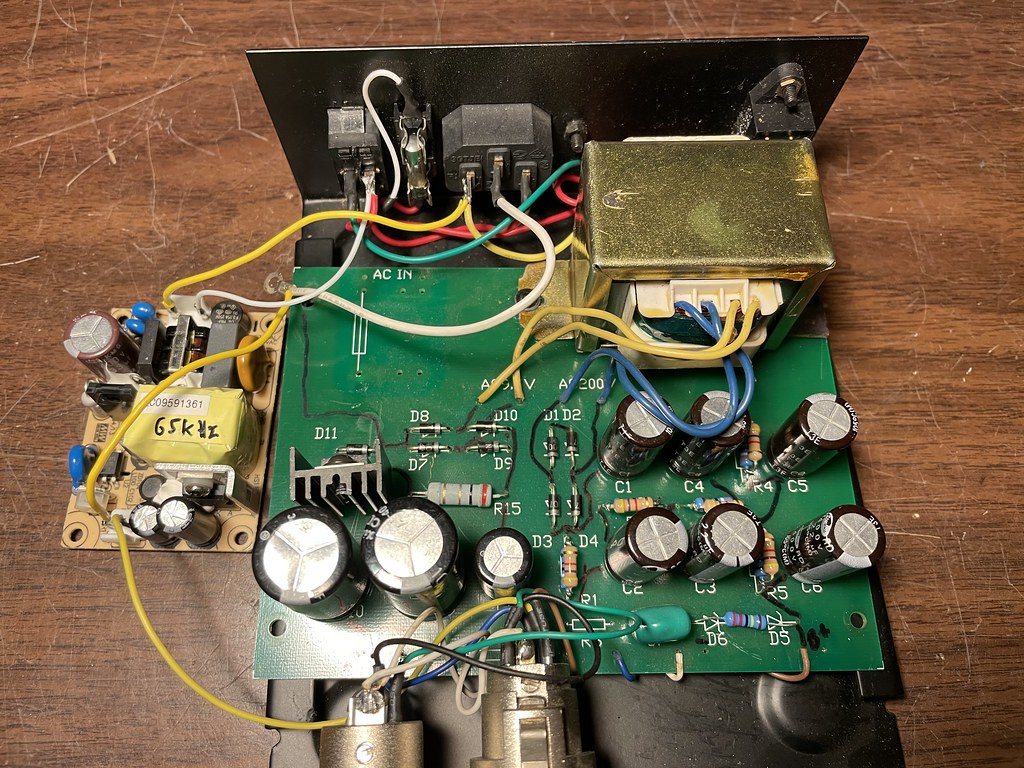
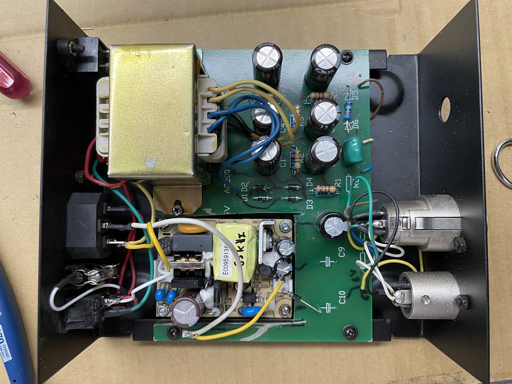
Update: in the end I've hacked the filament portion of the PCB out and added a Mean Well EPS-15-7.5 switcher for the filaments.  2A continuous and adjustable, and only $8.38.  Retained the final output filter cap and used diode voltage drop to get it more in range, though it was already silent without a cap.  No detectable heat production, and takes a bit of load off the power transformer which I've already pushed by asking for 8mA.  Maybe 3-4V increase on the B+. 

I took the last pic moments before I realized I hadn't reversed the electrolytic polarity for + ground reference.

ALSO:  note the position for the fuse on the PCB, and the place I've moved it to.  This fuse was NOT wired into the circuit at all! 

51125315850_595efc18da_b.jpg


51124255334_0c2e8b2a63_b.jpg
 
EmRR said:
Update: in the end I've hacked the filament portion of the PCB out and added a Mean Well EPS-15-7.5 switcher for the filaments.  2A continuous and adjustable, and only $8.38.  Retained the final output filter cap and used diode voltage drop to get it more in range, though it was already silent without a cap.  No detectable heat production, and takes a bit of load off the power transformer which I've already pushed by asking for 8mA.  Maybe 3-4V increase on the B+.
Nice. Gotta love SMPS.

For a few extra parts you could do a two transistor capacitance multiplier. It would be two diode drops which nails 6.3V pretty much exactly and you isolate the filter cap from the SMPS which can be a problem on startup. But if it works and it's already silent, then carry on ...
 
squarewave said:
Nice. Gotta love SMPS.

For a few extra parts you could do a two transistor capacitance multiplier. It would be two diode drops which nails 6.3V pretty much exactly and you isolate the filter cap from the SMPS which can be a problem on startup. But if it works and it's already silent, then carry on ...

Interesting!

I think I will do the same in my next project. Another tube hobbyist reaches the modern era. 8)

Therefore I would need a circuit design for a small add-on board, which integrates filtering, the prevention of hickup mode and additionally a status indicator.

Would the attached circuit basically fit if you add an LED with series resistor?

Obviously one would omit the rectifier, the 10kuf cap and further components needs some adaption and ready would be the modern HQ universal Switcher PSU to stone age heater circuit? (6 or 12Volt, max. 4A)

Cool or overkill?

(Schematic from here: https://sound-au.com/project15.htm )
 

Attachments

  • p15_fig4.gif
    p15_fig4.gif
    5.3 KB
I haven’t had any of about 4 types of Mean Well freak out from any environment I’ve stuck them in yet.  None I’ve tried seem to need external minimum load (data sheet) or have hiccup recovery problems.  I forget the overload capacity and timing on this one but it’s significantly higher than the steady state demands. 
 
rock soderstrom said:
Cool or overkill?

(Schematic from here: https://sound-au.com/project15.htm )
To make a heater supply from an 7.5V SMPS, you don't need nearly as many parts. You would literally need 6 parts: the 2 transistors, the R and C on the base, the protection diode and the 1000u on the output. Although it's just about enough parts where I would make a PCB in which case you could add the 12k bleeder to make sure the base goes to 0V. And maybe a 100uF on the input between the SMPS and the emitter of the pass transistor. For an LED just add a resistor and LED in series to the output.

Personally I would make it SMD (for any non-signal stuff I pretty much always lean SMD these days) with a huge area of double sided planes with lots of vias for the collector of the pass transistor. Then you don't have to worry as much about heat sinking and bolts and such. Of course without a large block of aluminum you can only put so much current through. But it should be able to handle what the EPS-15-7.5 can supply which is only 2A. You could probably even make the pass transistor SMD like a SOT-252-3 or DPAK-3. For high power transistors like TIP36 they're not SMD per-se. But if it's just a metal tab with a hole, they can be used as such. You just make a large wire pad in your layout software where the hole in the tab is (which is almost always connected to the collector but check this for whatever transistor you use). Then you just stick your iron in the holes and let it sit there until it starts to wick up solder. Again, no bolt necessary. For more than 5A or so, you'll need to just put the pass transistor on the edge so that it can be mounted on some large metal surface like a block of aluminum which is in turn mounted to the chassis. For easy retrofitting, you might place the transistor on the bottom of the board so that it can be soldered under the PCB sticking down but bent over parallel to the bottom of the PCB and then mounted to something such that the overall footprint is really small (could probably be as small as 1"x2" or so). Leave a hole in the PCB for the screw driver so that you can insert the transistor bolt from the top instead of using a nut without bending and unbending the transistor leads.
 
EmRR said:
I haven’t had any of about 4 types of Mean Well freak out from any environment I’ve stuck them in yet.  None I’ve tried seem to need external minimum load (data sheet) or have hiccup recovery problems.  I forget the overload capacity and timing on this one but it’s significantly higher than the steady state demands.

Yes, I have also noticed that you have been successful using SMPS in your builds for quite some time. You are my positive role model, so to say.  ;)

I will use more SMPS in the future, because I am tired of not having the right transformer.

The other advantages especially for tube heating are obvious.

The key to success seems to be to oversize the SMPS in terms of power performance. Then there are no problems with the cold heating at the moment of switching on.
 
squarewave said:
To make a heater supply from an 7.5V SMPS, you don't need nearly as many parts. You would literally need 6 parts: the 2 transistors, the R and C on the base, the protection diode and the 1000u on the output. Although it's just about enough parts where I would make a PCB in which case you could add the 12k bleeder to make sure the base goes to 0V. And maybe a 100uF on the input between the SMPS and the emitter of the pass transistor. For an LED just add a resistor and LED in series to the output.

Personally I would make it SMD (for any non-signal stuff I pretty much always lean SMD these days) with a huge area of double sided planes with lots of vias for the collector of the pass transistor. Then you don't have to worry as much about heat sinking and bolts and such. Of course without a large block of aluminum you can only put so much current through. But it should be able to handle what the EPS-15-7.5 can supply which is only 2A. You could probably even make the pass transistor SMD like a SOT-252-3 or DPAK-3. For high power transistors like TIP36 they're not SMD per-se. But if it's just a metal tab with a hole, they can be used as such. You just make a large wire pad in your layout software where the hole in the tab is (which is almost always connected to the collector but check this for whatever transistor you use). Then you just stick your iron in the holes and let it sit there until it starts to wick up solder. Again, no bolt necessary. For more than 5A or so, you'll need to just put the pass transistor on the edge so that it can be mounted on some large metal surface like a block of aluminum which is in turn mounted to the chassis. For easy retrofitting, you might place the transistor on the bottom of the board so that it can be soldered under the PCB sticking down but bent over parallel to the bottom of the PCB and then mounted to something such that the overall footprint is really small (could probably be as small as 1"x2" or so). Leave a hole in the PCB for the screw driver so that you can insert the transistor bolt from the top instead of using a nut without bending and unbending the transistor leads.

Thank you for your detailed answer and the numerous suggestions!👍

I will get some SMPS and test them through and see what I really need to integrate them reliably and quietly into my circuits.

This will be exciting and a first use for my new computer based "measurement system".

Signal analyzer to the front!
 

Latest posts

Back
Top