tube power supplies, switchmode

GroupDIY Audio Forum

Help Support GroupDIY Audio Forum:

This site may earn a commission from merchant affiliate links, including eBay, Amazon, and others.
kambo said:
pretty much using what i have ... happy to try ur suggested drawing for measurements!
For test the effects of load and ripple you want to do something like this:

SmpsLoadTest.png


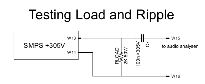
Be careful the load resistor doesn't burst into flames.

More generally, a good external supply might look something like this:

SmpsExample1.png


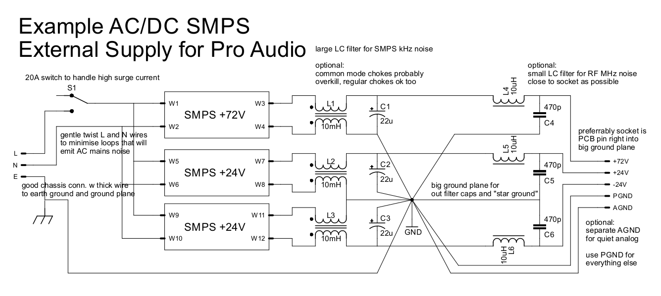
I'm not suggesting that you do this. It's just what I would consider to be a good example of an external supply for pro audio using SMPS like the ones you're testing.
 
The combination of common and differential mode filters on the outputs seems to be the way to go alright , there is one company who makes a hybrid com/diff inductor on the one core ,mainly for space saving .Seeing as the current is fairly low on a ht supply ,thinner wire with many turns might be worth looking for .
 
The example supply in my graphic is relatively low voltage. Again, that example is not specific to the particular high voltage SMPS discussed in this thread (I figured I can reuse that graphic in another response - there have been quite a few SMPS questions lately). But the filtering would be the same and yes, the chokes would need to be selected based on current required.

Actually the choke voltage rating could be an issue for high voltage supplies. Many chokes are limited to ~250V or so. And unfortunately it's not a searchable parameter on Mouser.

For the +-24V and +72V supply in my graphic I would use something like ALFT-03A-8 which is 5.5mH 1A 0.75ohms and for the RF chokes they can be little guys like Murata LQH43PN100M26L which are 10u 1.05A 0.127ohms.

Note that there are SMPS that are 48V exactly. But I regulate down inside each unit using a linear regulator. Dropping from 72 to 48 is no problem if it's just a few mA for a phantom supply. Or instead of +-24, you could do +-30V and then stack another +30  to get to 60V. That way you can also get regulated 24V which a lot of stuff uses.
 
hey squarewave, thanks for the drawings!
dont have hefty 2k resistor handy...
made a quick measurement with 2.5k (10W resistor is getting smokey pretty quickly)

it measures 0.08VAC with 2.5k load resistor...
will try hook it up to sound card, for a quick snapshot!
 
placed 1:1 trx incase something goes wrong  :eek:
this how it looks...
(loop back  0dbfs  out = 0dbfs in)
blue base line is loopback noise. this should give u an idea!


Attachments

  • measurement.png
    measurement.png
    98.3 KB · Views: 13
this with 2.5kload and 470uf cross the output
lot of cables etc noise too!
and no proper grounding etc on all screenshots!


Attachments

  • with 470uf.png
    with 470uf.png
    96.3 KB · Views: 12
Hmmm interesting stuff Kambs ,

Looks like an LF choke and large filter cap could give some extra smoothing in this case ,I'd say one CLC PI would certainly snuff out what remains of anything in the audio band . Be interesting to see whats going on at supersonic frequencies too .
 
kambo said:
placed 1:1 trx incase something goes wrong  :eek:
this how it looks...
(loop back  0dbfs  out = 0dbfs in)
blue base line is loopback noise. this should give u an idea!
Looks good. Most of that 60Hz and 120Hz is also in the loopback plot so that's probably coming from the PC. When using a sound card you're limited to comparative measurements but it did the job in this case. I would say that SMPS is good to go.

This is Mean Well ELG-150-C500A we're talking about right?

PS: So does the voltage drop at all when you add the 2k5 load (122mA) ? I think you said "no" before but was that with the 2k5 load?
 
squarewave said:
Looks good. Most of that 60Hz and 120Hz is also in the loopback plot so that's probably coming from the PC. When using a sound card you're limited to comparative measurements but it did the job in this case. I would say that SMPS is good to go.

This is Mean Well ELG-150-C500A we're talking about right?
yup!

squarewave said:
PS: So does the voltage drop at all when you add the 2k5 load (122mA) ? I think you said "no" before but was that with the 2k5 load?

no voltage drop with 2k5 load either


squarewave said:
Does the current adjust pot affect the loaded output voltage in any way?

ohh, totally forgot to fiddle with that... will do in the morning!
 
kambo said:
ohh, totally forgot to fiddle with that... will do in the morning!

fiddled with the trimpot on the bottom... voltage is not changing
i also placed an amp meter between "+" of supply and resistor connection, it was measuring 0.125 ADC,
no change with trimpot either!
 
kambo said:
fiddled with the trimpot on the bottom... voltage is not changing
i also placed an amp meter between "+" of supply and resistor connection, it was measuring 0.125 ADC,
no change with trimpot either!
That’s good. That is what is expected I think. Presumably when enough current is being drawn the voltage will start to drop depending on that pot setting. That’s for dimming when used with a bunch of leds. Not sure if it would allow for adjusting the voltage in a tube circuit. Not unless your drawing > 250mA.
 
found couple more 5K 5W resistors  8)
with 1.25K load resistor voltage is dropping, and was able to rise it a little with the trim pot,
also lover it down to 92 VDC!
at this point resistors starting to cook pretty quickly, couldnt make proper measurements...
will try again once they cool down a bit!
 
with 1.25k load resistor
trimpot factory set point (around 3'clock) : 195VDC
CCW : DMM having difficulty reading data at full_ish ccw: around 9'clock i start reading 90VDC...
CW : 240VDC
 
Mmm, 240V / 1.25K is only 192mA but the datasheet claims it can do 500mA with the current adj. full CW. So something is a little off.

According to this from the datasheet:

SMPSrating.png


output voltage (Vo) should be a solid 100% well up to within at least 80% of the 500mA limit. But you're only getting 240V at 192mA and 90V at 72mA. Weird. The circuit is just like in my drawing right? Your not dropping voltage across another resistor somewhere right?
 
squarewave said:
Mmm, 240V / 1.25K is only 192mA but the datasheet claims it can do 500mA with the current adj. full CW. So something is a little off.

According to this from the datasheet:

SMPSrating.png


output voltage (Vo) should be a solid 100% well up to within at least 80% of the 500mA limit. But you're only getting 240V at 192mA and 90V at 72mA. Weird. The circuit is just like in my drawing right? Your not dropping voltage across another resistor somewhere right?

yup, circuit is just like in ur drawing...
10w resistors cooking pretty quick.. couple already dead...
i have some 1/2k - 20w resistors somewhere... i will double check with them, i should have more time
to play with values/measurements, before they start cooking!


kambo said:
yup, circuit is just like in ur drawing...
10w resistors cooking pretty quick.. couple already dead...
i have some 1/2k - 20w resistors somewhere... i will double check with them, i should have more time
to play with values/measurements, before they start cooking!
I bet. 240 / 1250 = 0.192 * 240 = 46 watts. Take care.
 
before the cooking procedure;
last time i measured them:  1150r to be exact!
around 50W
poor resistors :eek:

this thing is actually pretty powerful for 305VDC...
kind i curious... is it safe to use it in an audio equipment...
incase something goes wrong, while touching multiple conductive surfaces, etc!

edit : typos
 

Latest posts

Back
Top