Two-tube mic preamp idea

GroupDIY Audio Forum

Help Support GroupDIY Audio Forum:

This site may earn a commission from merchant affiliate links, including eBay, Amazon, and others.

blandman74

Well-known member
Joined
Aug 4, 2005
Messages
67
Location
Washington, DC
I figured I would ask around if anyone has seen this kind of design for a mic amp, and if my calculations on the gain, etc., are close. Most of the info I used in putting together the first stage I got from the tech pages at Aiken Amps, esp. here:

http://www.aikenamps.com/FeedbackAmp.htm

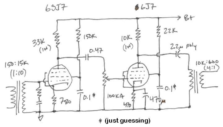
But that page does not address using feedback on a pentode stage. I love the sound, to the extent my amateur ears can detect it, of pentode stages, so I wrote this one out:

InvertingFBAmpdesign.jpg


If I have the gain calculations on this right (open loop it would be over 200 in gain, but with feedback it runs about 51), then it gets a health amount of gain but still uses some feedback to tame noise a little bit. But I still have a lot to learn about noise.

Curious what others think.
 
There are some problems with this circuit. First off, the gain of the pentode will be pretty close to Rfeedback / Rin, or 470k / 12k from the secondary of the transformer to the pentode's output.

But having the input resistor in series with the grid does two things: it adds a good deal to the noise, and it mis-terminates the transformer. You mentioned an input Z = 8k; I would expect more like 12k, but let's go with 8k. You also mentioned a 1:4 turns ratio; for a 150 ohm source that would mean an output Z of 150 x 4^2, or 2400 ohms. Most transformers want to be terminated by 10x the Z of the secondary, which would mean a termination resistor of 24k, not 12k or 8k. Either of the latter would severely overdamp the transformer, causing the high frequency response to droop. It would also give you an input Z at the primary of 750 ohms, which would make an SM57 happy but would be too low a load for most condenser mics to be happy.

That's not the biggest problem, though. The biggest problem will be noise. Ideally the electronics add very little to the inherent noise of the souice. Assuming a perfect transformer (there ain't no such thing, but never mind) with a 1:4 turns ratio, that would be an output impedance of 2400 ohms. Add to that, however, the impedance of the feedback network, which is 12k paralleled with 470k, or about 11.7k, for a total Z of about 14.1k. This is about 5.9x the impedance of the transformer by itself, and the noise performance is proportional to the square root of the impedance, so the noise contributed by the microphone, transformer and feedback network will be sqrt(5.9) times as bad, or about 2.4x as much noise, or about 7.7dB of excess noise even before the pentode gets done adding its contribution. Not good.

This is why inverting-feedback circuits like this aren't used in places where noise is an issue.

Peace,
Paul
 
Paul covered it, and I'll add that one seldom finds feedback on the first stage of a tube preamp, especially localized. There are a few cases I can think of, and they used only 1-2 db in local loops at each tube. There's also a fairly obscure single pentode 6J7 RCA preamp from WWII era that uses a similar method, but it is intended as a line buffer isolation amp rather than a preamp.
 
Thanks. I had a feeling that that input resistor would cause noise problems.

I set the input transformer to 1:4 because I was thinking of the termination issue, although maybe I was getting the math a little wrong. I guess a 1:2 turns ratio input transformer would have helped reduce the first problem pointed out by Paul? That is, a 150 input Z resulting in a secondary of 600, so that a mic would "see" an input Z at the primary of about 2k, if we assume that my Zin calculation before the 12k resistor is in fact 8k. As for termination of the secondary, I thought that the design cleverly terminates the secondary through the feedback resistor and load resistor (pot), resulting in well more than a 10x termination. Sounds like I am wrong about that.

Anyway, noise problems put an end to this design for me. I am going to have dig into that stuff deeper.
 
Dead-horse whipping:

Set the 1Meg pot halfway up. The wiper is at least 250K impedance.

Two of 6SN7, Cgp=4pFd Mu=20 with this loading will give gain near 15. The 8pFd of combined Cgp will give around 8pFd*15= 120pFd input capacitance.

Against the 250K pot wiper set near -6dB, 120pFd is down 3db at 5.3KHz. However near -20dB it will be ~10KHz. Hard to say what the treble is at full-up... I don't think you have "ample" NFB around that stage.

Pentodes have higher voltage noise than triodes.

Low cathode current gives higher voltage noise.

A good rich triode can get away with a 1:4 or 1:7 input transformer (assuming 150 ohm source) at low noise figure. To do this at lower currents, 1:10 and even 1:15 transformers were used in consoles. A pentode is liable to have even higher voltage noise, but we can't wind higher ratios. 1:15 from 150 ohms is already 34K and stray capacitance will trim the highs.

> I love the sound,.. of pentode stages

So use a pentode. But use hi-ratio iron, and run the pentode rich. Like 3mA. That happens to be a book condition: 100Vp, 100Vg2, -3Vg1, 1,575uMho, 2.9mAp, 0.9mAg2. So assumed a 250V supply, the plate resistor is 150V/2.9mA= 33K, G2 resistor is 150V/0.9mA= 150K, cathode resistor is 3V/3.8mA= 780. Now you can hang a 100K gain pot on it. The combined load is 33K||100K||0.7Meg= 24K, gain is 37. The worst-case pot treble loss is -3dB at 40KHz, -1dB at 20KHz.

I suspect that a selected 6J7 or 6SJ7 will give noise figure approaching 5dB. Which is not as bad as you'd think looking at boastful spec sheets. Most transistor inputs degrade significantly when gain is less than MAX.

Maximum input voltage is near 4Vpp or 1.4Vrms, 140mV at the other side of a 1:10 input tranny. That used to be "huge"; in today's studio, it isn't. Triode-strapping the pentode will drop gain 8dB and give just that much more input headroom, plus lower noise. Un-bypassing the cathode resistor will drop gain another 6dB with negligible increase of noise.

6J7 triode can do the output stage too. Try 15K plate resistor, 6mA idle, ~780 ohm cathode resistor. Expect gain of about 12 to plate and 3 through a 10K:600 tranny. Or as Pentode: try 10K plate, 22K screen, 470 Rk. Gain will be similar. Over +20dBm max output.

These changes put you to 2 or 3 times the supply current of your original plan. In large consoles, that added up, so they didn't brute-force this way. In small DIY, you can do it.
 
Hey, thanks!

I don't think you have "ample" NFB around that stage.

Are you suggesting that one of the benefits of feedback is that it reduces or neutralizes input capacitance? If so, how?

Low cathode current gives higher voltage noise.

A good rich triode can get away with a 1:4 or 1:7 input transformer (assuming 150 ohm source) at low noise figure.

And here, are you suggesting that a higher turns ratio reduces inherent noise of the pentode stage, or are you saying that a higher turns ratio just makes the source noise overwhelm the voltage noise of the tube?

So use a pentode. But use hi-ratio iron, and run the pentode rich.

So if I have it right, you're saying that a pentode's noise characteristic (compared with a triode) can be offset by using a high turns ratio input transformer into a high-current input stage.

I really appreciate this - finding good source material from which to learn about noise, and how to think about minimizing it, has been tough.


Slightly edited ...

... and here is a sketch-up of what I think PRR is suggesting.
DualPentodemicpreamp.JPG
 
> makes the source noise overwhelm the voltage noise of the tube?

That's how it's done.

My guess is the first cathode wants a bypass cap for lowest hiss on small sources.

Screen caps should be like 1/20th of cathode cap (because Mu is near 20). Your 470uFd is obscenely high by ancient standards; 20uFd would be ample. Then that screen cap wants to be 1uFd. Indeed 0.5uFd was used on hot-run small pentodes. It is yet another reason why a twin-triode is hardly any more expensive than a pentode stage. 0.5uFd in Film is big and costly. With modern low cap prices, you could do 470uFd/20= 22uFd 400V Electrolytic; with a 22K screen resistor, modern electro leakage won't be a problem.

BTW: ideally the screen cap returns to cathode not common. With your honking big cathode cap value, it may make no difference at all. We usually wired whichever way was easiest. Small caps fit nice on the socket, big caps go off-socket and generally wind up at common.

BTW: 6SJ7 and 6J7 are the "same" tube. When new, fashion dictated grid-caps, 6J7. A few years later, fashion switched away from grid-caps, buzzword "Single ended" (not same meaning we know today), and a bunch of old tubes got sisters with "S" in the name and grid on a base pin, 6SJ7.

The top-cap versions look more exotic to modern eyes (in the 1950s we thought they looked ludicrously obsolete), are often very high quality mid-1930s production, and you can quick-test a dead amp by putting your finger on grids. (Do NOT try this on plate-cap power bottles.)
 
Hi,

This is an old topic but I am building this simple preamplifier with EF22 I have extra.

I have recalculated the 6SJ7 version according to:
http://www.valvewizard.co.uk/pentode.html

S1206_KM_C216071910580_0001.jpg


here is another source for a similar schematic:
https://sites.google.com/site/doorstopelectronics/home2

Note changes, mainly I had to change the Ra for the second stage, since the Ia was off the diagram. And connect the CRg2 to Cathode, not ground. Frequency for the caps is 10 Hz. I have not made changes to the coupling caps. You can use a 1M lin pot with a 220k resistor conected to the wiper and ground to make it logarithmic, I  guess.

I will report on my progress, I just need to change a few values of components and build a better supply. Maybe even puting the tube sockets on silent blocks, so it can withstand some vibrations.

All input welcome :)  8)
 
Are you planning to use EF22 or 6SJ7? EF22 is variable MU pentode and will have high distortion. If using 6SJ7 for the first stage I would take the resistor values from resistance coupled amplifier chart for 6SJ7. Every example in the chart for 300V Ebb will have lower distortion than your plan. Or will your plan have less noise because the tube is running at higher current? Or will it be noisier because of the higher screen current?
 

Attachments

  • rca_c20.gif
    rca_c20.gif
    34.4 KB · Views: 24
Heikki thank you for reply!

I did not know there is such a table (resistance coupled amplifier)!!! Why do I find out only now? :)

Anyway I plan on using the EF22, just to see if my calculations are correct. I will do that today, and let you know how it turned out.

btw are you from Finland?
 
Ok, built it (with EF22), some pictures from scope. At the end you can see CH1(out yellow) and CH2 (in blue) at 1kHz and 10kHz.

Some basic measurments:

B+ voltage was 282V (Calculated for 350V)

At very low input:
60 Hz -1,6 Vrms (here the waveform is still a sine, anything below it just breaks)
100 Hz - 2 Vrms
1000 Hz - 2,67 Vrms
2000 Hz - 2,75 Vrms (here the value breaks from 2,8 Vrms)
5kHz - 2,8 Vrms
10 kHz - 2,8 Vrms
15 kHz -2,8 Vrms
20kHz - 2,8 Vrms

This was very low input (doh, forgot to measure!) maybe it was a problem of the generator, since it is a simple XR2206 generator.
The generator also creates a spike on the top of the curve (usualy visible only through analog scope)

I had also a feeling the signal at low input is beeing modulated by 10 Hz.


EDIT:
The schematic I built, now that I look at it I shoul add a grid leak for g1 (1M, is it still necesary when using 1:10 trafo?) and I used a 10k Potentiometer (only one I had laying around)=CR High Pass Filter 33Hz cut off f. As oposed to 1M Pot=0.33 Hz cut off f.


btw: I tested with monacor DIB-110 1:10 trafo at both input and output, and they seem fine for the preamp. And good price.
 
Hello everyone. I have a pair of LMT 3328A tubes. Please advise about this ball in case I want to replace the 6J7 bulb is it possible or not. Thank you.
 
Back
Top