Using a power supply as both bipolar and single rail.

GroupDIY Audio Forum

Help Support GroupDIY Audio Forum:

This site may earn a commission from merchant affiliate links, including eBay, Amazon, and others.

trashcanman

Well-known member
Joined
Jan 26, 2016
Messages
104
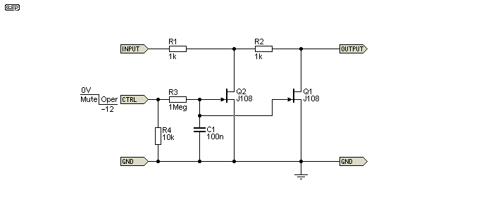
So I'm building a summing mixer using a LAWO DV975 summing module and need a power supply to power both the module and the mute circuit I'm using for each channel. I'm using this jfet circuit for each channel mute
yWjoPsG.gif


It needs a negative voltage to deactivate the mute. The summing module runs on +24v and 0V.
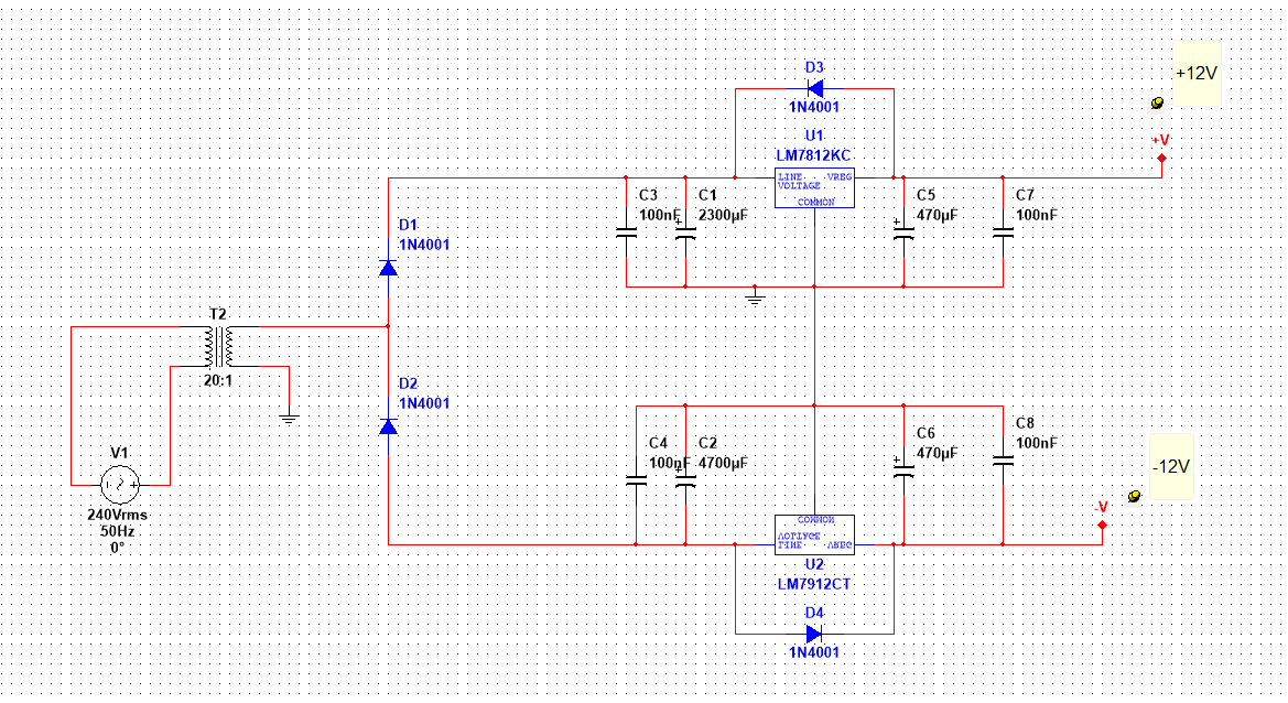
Here is a vague schematic of the power supply I was planning to use.
mHoNgIc.png


It's a full wave voltage doubler which gets me + - 12V which I figured I could use for the module and the mute circuit but thinking about it again I'm not sure I can.
While there is a 24V difference between the two rails I think my ground references will be messed up if I connect the -12V rail as 0V on the module. Would this be the case or could the LAWO run on a floating ground?
 
You know that you don't have to use n-chan JFETs. You could use p-chan like J176 / J175 and then 0V is mute and +12V (or +24V) is oper. Same exact circuit.
 
Well that solves that problem I guess. It seems to work fine with the PNP in my simulation but I'm still unsure how the grounds are handled with this kind of power supply. I should be able to leave ground, 0V and Safety Earth all unconnected to from other, correct?
 
You could run your module between +12 and -12. That's makes 24V alright. But if -12V relative to the transformer ground is connected to 0V of the module, you have to make sure you don't accidentally connect that back to the transformer ground such as through the chassis. That would short out the -12V rail.

Generally speaking this sort of thing is not recommended largely because it's just not necessary (center tapped / split transformers are common). It can be done successfully but there are several nuances that can be difficult to get right. For one, you will have the potential for noise because your module ground is now "standing" on the -12V rail. Usually this is done a little differently by making a virtual ground with a voltage divider and large coupling cap between the two "grounds". Meaning make the standard 24V supply and then "split" that to make a virtual 0V. Technically these two scenarios are actually the same so nuances abound.

So if you don't need a bipolar supply, then you should just make standard 24V supply and use p-chan JFETs for your mute circuit.
 
Hello

Don't know precisely the DV975, do you have a schemo ?
Usually for this kind of broadcast modules powered from +24V there is on board regulators or rail split for "virtual" ground
So you should have somewhere a 0/12/24V... +12 being Vref or "ground"... if you float your mute circuit at it, N channel will work as it should with relative -12V (the PSU or regulator 0V)

Best
Zam
 
trashcanman said:
It's a full wave voltage doubler
No it's not, it's a half-wave rectifier.
Why do you want to use such a pityful PSU. If you useed a 24V xfmr, you'd have a nice +30V unregulated and a -15 also.
 

Attachments

  • dual rail from single secondary.jpg
    dual rail from single secondary.jpg
    44.9 KB
This module draws only 100mA, so IMO the simplest solution is using the halfwave rectifier+regulators from the first post where the secondary voltage is 24Vac, upper reg is 7824 (for DV975) and lower is 7912 (for mute circuitry).
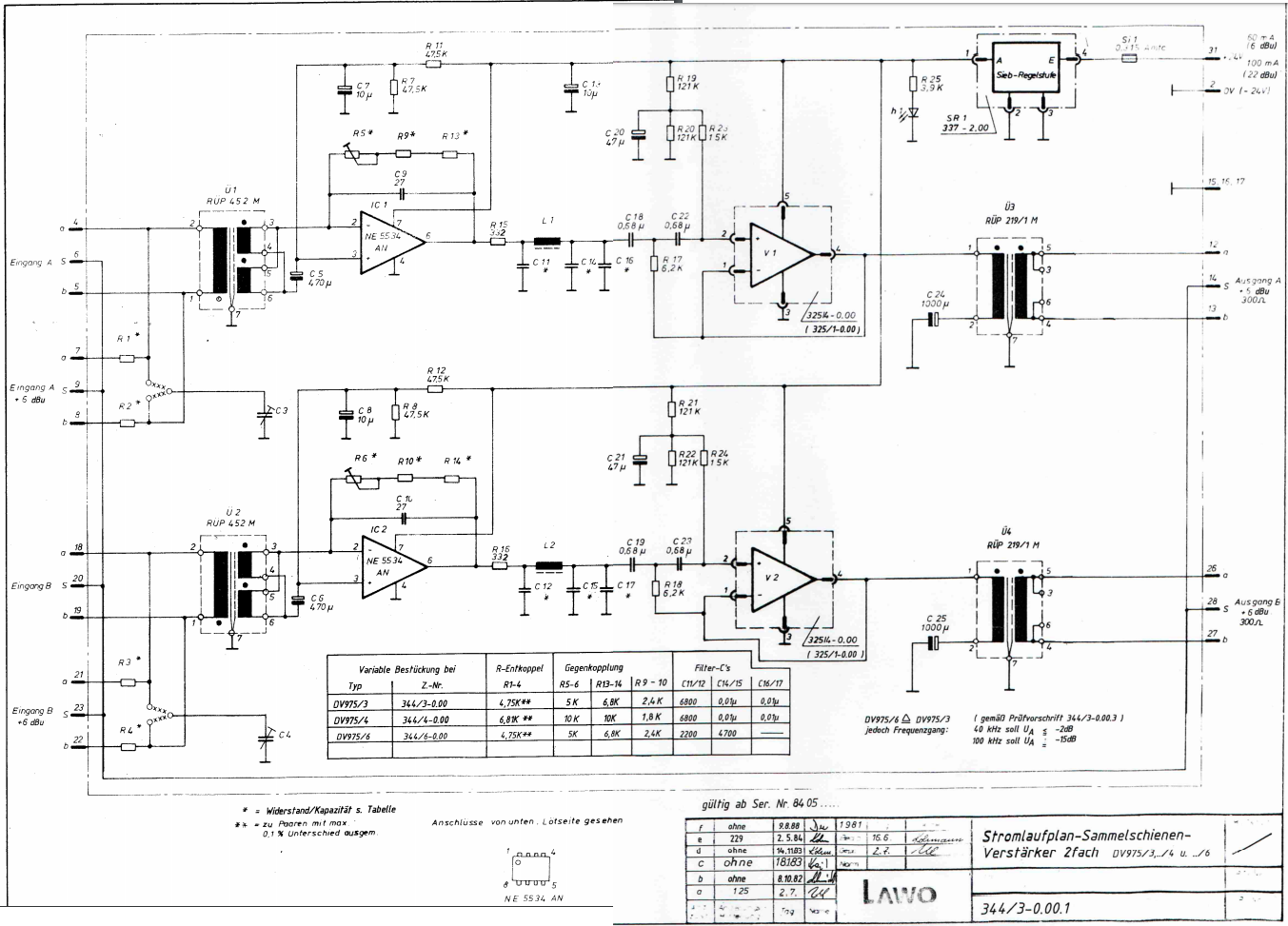
The schematic of DV975 can be found on Kubarth site.

@abbey
You have some redundant diodes in your schematic :)
 
moamps said:
The schematic of DV975 can be found on Kubarth site.
Here it is:

LawoV975.png


Trashcanman should post a full schem of the project. Otherwise, we're really spinning wheels and potentially giving out bad advice. Aside from the fact that if the mute circuit is outside the transfromers, it doesn't need a virtual ground at all but perhaps more important, it's also not crystal clear to me that that mute circuit would even work with a transformer summer. I would need to see a complete schem to comment further.
 
moamps said:
This module draws only 100mA, so IMO the simplest solution is using the halfwave rectifier+regulators from the first post where the secondary voltage is 24Vac, upper reg is 7824 (for DV975) and lower is 7912 (for mute circuitry).
The schematic of DV975 can be found on Kubarth site.

@abbey
You have some redundant diodes in your schematic :)
Yes, that's because I favour bridge rectifiers, even when I don't need the whole package.
 
Back
Top