Using the JLM PSU to power a 312 clone...

GroupDIY Audio Forum

Help Support GroupDIY Audio Forum:

This site may earn a commission from merchant affiliate links, including eBay, Amazon, and others.
Joe, you mentioned putting a load resistor on the regs to keep them happy.

I haven't done enough of this stuff for it to be second nature, I'm thinking transformer termination load resistors running from hot to cold, then again op amps sometimes like a load resistor in series on the outs to keep them happy.

:?:
does a load resistor on a power supply go from rail to rail, or is there one on V+ and one on V- each going to ground?

I'm building a dual psu, an 18v+- and a 15v +-, the 15 volt runs a headphone amp and i'm using PRRs Tori amp which runs really hot when it's not in use, so I thought I'd switch off the DC legs when it's not in use. I thought I'd short the + and - to ground through a resistor when it's in the off position.

edit:
this is I guess just a theoretical question now that I came up with a better solution. I'll run my meter lamps off the 15 so theres always a load on the regs.
edit edit:
oops, this just keeps a load on the plus side don't it.
I still need a load resistor on the neg.

Thanks
Sleeper
 
Joe, you mentioned putting a load resistor on the regs to keep them happy.

The load resistor is only if you use a TL783 for the 48v regulator instead of the LM317. As the TL783 must have a load of 15mA to regulate or its voltage will float to the full unregulated power rail voltage (ouch). The 120ohm and adjustment trim pot draw 10mA so the load only needs to draw 5mA. So 48v/5mA= 9600ohms. So use the next standard value down = 9.1k or 8.2k between 0v and 48v output.

With normal 78XX/79XX or LM317/337 series there is no need for any extra load resistor. When you switch your headphone amp off there is no need to add a load either. Be careful when swithcing the +/- rails with a DPDT switch as the headphone out will put one massive thump which could easily kill your headphones or your ears.
 
Also, you should be able to run the Green Pre on 18V without a problem.
If you have the Green-version with the LED-meter, just be sure to adjust the trimmer to recalibrate the LED-thresholds.

Maybe use a little less than +/-18V since this is the max. rating of the LM339-IC (I should check the schematic, maybe that 36V it's not fully across the '339).

Regards,

Peter
 
Thanks Joe,
A Massive Thump.
I'll have a look about for some thump protection.
I know I've seen it around.
Glad I asked, it's sooo much better than smoke testing.

All the best
Sleeper
 
Well, I?ve considered the many options Joe gave to solve the problem, and I really prefer the last one, although it requires a TL783 which are long gone. I know you can find them from time to time, but it seems that a LM317 will still work as long as I get the LM317HVT version (still available through Digi-Key).

Here is the thread that talks about that:
http://www.groupdiy.com/index.php?topic=4992&highlight=tl783

So the LM317HVT can dump up to 60V, and in this particular application, it will be dumping around 37 V. I?m gonna be case mounting all three regulators since I can?t squeeze in heatsinks of appropriate sizes.

So, just to sum up the mod, since this isn?t my area of expertise, and I?d hate to ruin such a nice power supply!

I?m gonna run a 30 VAC center tap power transformer. One winding to AC 0V, center tap to AC in, the other winding to the + pad of one of the pump charge caps (C1). Both caps stay in place, correct? Also, switch out the 36V Zener for a 1n4002, and replace the LM317 with a LM317HVT.

Did I miss anything?

Everyone, thanks for all the help!
Andrew
 
Did I miss anything?

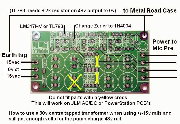
No but I did stuff up in my earlier post. As leaving out the cap would have disabled the pump charge so a 44 to 48vac winding would have been needed for the 48v rail.

But the jpg below shows how to do it without having to wire to anything except the terminal blocks and will work with the 30vac centre tapped transformer idea. The parts marked to NOT be fitted must be removed or not fitted for this to work.

JLMACDClv48v.jpg
 
Sweet. I was a bit confused, cause you said take the lead to the + side, which if the caps are in place, didn't make sense, and without the caps, the pump cahrge would be gone, as you just said. The JPG didn't show, but I'm looking forward to seeing it, as the solution seems to be quite easy, and avoiding putting a second transformer in this box is gonna make my weekend!

Thanks again
andrew
 
Well, I've been wracking my brain for the last day over this mod. I was hoping to understand how it works, at least to a basic degree, before I build it. If I'm not mistaken, the changes can be seen here:

http://www.oddharmonic.com/DIY/ACDC-mod1.gif

Can anyone shed some light on the following questions?

Wiring one of the 15 V windings to the 0 VAC input makes no sense to me. That is a reference ground for the DC outputs, and it is now connected to an AC winding? Confused....

Now, the bi-polar 15 V part I understand, although this method uses only one winding, making the ripple twice as much, correct? Will this have a serious effect on the final regulation? Will there be a noticable drop in performance from the mic pre with this change? Also, am I correct to think that a 50VA power transformer will only make 25 VA available for the +/- 15 V if only one winding is in use?

For the 48 V section, I'm at a loss at how this works. The idea was to shove 30 V into the pump charge, giving plenty of headroom to regulate down to 48V. I don't see how this works at all.

Thanks for any help that comes my way
Andrew
 
Well, I've been wracking my brain for the last day over this mod. I was hoping to understand how it works, at least to a basic degree, before I build it. If I'm not mistaken, the changes can be seen here:

http://www.oddharmonic.com/DIY/ACDC-mod1.gif

Can anyone shed some light on the following questions?

Wiring one of the 15 V windings to the 0 VAC input makes no sense to me. That is a reference ground for the DC outputs, and it is now connected to an AC winding? Confused....
Your gif above has a few mayor mistakes on it :)

The one below is correct and should make it easier to see what is going on.

Now, the bi-polar 15 V part I understand, although this method uses only one winding, making the ripple twice as much, correct?
Yes the ripple will be at 50 or 60Hz depending on the country your in and larger than the 100Hz ot 120Hz ripple if you had of used full wave.

Will this have a serious effect on the final regulation?
No as long as the low point of the ripple is about 3v higher than the regulated ouput at full load.

Will there be a noticable drop in performance from the mic pre with this change?
Final noise floor at 60hz & 120Hz may be slightly less.

Also, am I correct to think that a 50VA power transformer will only make 25 VA available for the +/- 15 V if only one winding is in use?
This is much more complicated to explain but the 50va should be fine even used this way.

Like I said further back on this thread. I would use the 36v centre tapped transformer you had and just set the 48v rail a couple of volts lower and it would have the less ripple due to the full wave and it also would have also worked fine. :wink:
 

Latest posts

Back
Top