UTC M-1433 OPT

GroupDIY Audio Forum

Help Support GroupDIY Audio Forum:

This site may earn a commission from merchant affiliate links, including eBay, Amazon, and others.

CJ

Well-known member
Joined
Jun 3, 2004
Messages
16,021
Location
California
got some fresh yank here, courtesy of the one and only Rackmonkey,

UTC output, used in the Collins mixer,  :D

25K to 600 with a bonus wind, F/B at 11 Ohms

it has been raining iron this last month, trying to keep up is like setting pins for an octopus at the bowling ally,  and nothing makes me happier, every day a new adventure, wonder what this guy will have up its sleeve,
 

Attachments

  • c1.JPG
    c1.JPG
    177.5 KB
freq response off the map, flat til 50 K, then a peak at 155 K then a nose dive never to return,

here is what we have so far>
 

Attachments

  • UTC M-1433.png
    UTC M-1433.png
    19 KB
Hey, howcome your TI-30XA looks different from my TI-30Xa?

Yeah, I know, the TI-30 changes every few years, even when TI doesn't say so. For a couple years the decimal point was much too small for >13 year old eyes, this latest one is some better.

Here's yours, my current, and what I used around 1980.


Attachments

  • TI-30Xa-3.jpg
    TI-30Xa-3.jpg
    38.4 KB
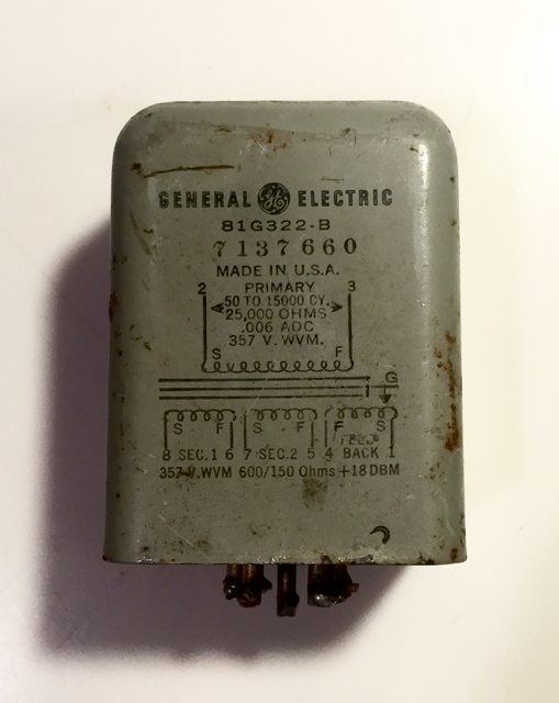
General Electric 4BA1H1 and 4BA3 preamp output.  Same circuit as Collins 356A except difference in primary ratio, almost same as Langevin 5116 (not -B).

Also 81G322-B and ADC A8547.
 
taking the lid off,

these lids are probably put on with a torch, then the can is painted, so you really need a torch to take the lid off, but you will lose the paint and silkscreen so a big iron on the hip is the way to go unless you are going to repaint the can.


Attachments

  • m1.JPG
    m1.JPG
    215.3 KB
there is a nested can for shielding,  unusual for an output,

maybe they anticipated this xfmr being used backwards as a mic input,

got the leads labeled but know we have to fold the labels to get them thru the lid holes, no big,

color codes were written down jic.


Attachments

  • m2.JPG
    m2.JPG
    191.9 KB
there is some black goo holding that guy in there which can be loosened up with the heat gun,
 

Attachments

  • m3.JPG
    m3.JPG
    186.9 KB
that 625 EI core is butt stacked in two sections,

that is probably the reason for the large leakage inductance, fringe flux around the gaps,
 

Attachments

  • m4.JPG
    m4.JPG
    161.2 KB
this steel likes a bit lighter than normal silicon,  but not bright enough to be Supermalloy.

it might be 50/50 Ni or some special blend made by Mag Metals for UTC.

since it is butt stacked, we do not have to destroy the lams to get it apart,


Attachments

  • m5.JPG
    m5.JPG
    199.8 KB
EI 625 = 5/8"  tongue, we have a 7/8" stack, which is a coil aspect ratio of 5 to 7 or .714

time to mount that bad boy on a mandrel and shim it up for dissection,


Attachments

  • m6.JPG
    m6.JPG
    244.3 KB
outside layer is the feedback wind, 84 turns,

the start and finish leads both had splices, so there is probably another 84 turns in parallel to keep the phase angle between the primary and F/B wind as close to zero as possible as frequency goes up, this keeps the amp stable,
 

Attachments

  • m7.JPG
    m7.JPG
    631.2 KB
we have a 2 mil soft copper shield in between the F/B and primary wind , this coil has been "engineered",  probably by the guys on the top floor since GE has some pull,


Attachments

  • m8.JPG
    m8.JPG
    216.8 KB
primary outer primary wind that will go in series with an inner wind, #40 to #42 AWG wire depending on who's wire chart you use,  we will try and figure that out by DCR,

partial finish layer, 83 T on the left, 43 T on the right,
 

Attachments

  • m9.JPG
    m9.JPG
    217.6 KB
this coil is old, so the layer insulation is not going to peel off nicely even with the heat gun , it is pretty crusty, so we have to pull the thin wire thru the paper and hope that it does not break.  it is hard to dig the lead back out from under the insulation without gouging into the next layer down and cutting wires,

so you heat the layer twice during unwind with the heat gun and use a slow speed, if it hangs up you have to train yourself to let go instead of pull harder, then you stop the machine, back wind a few turns and start again,  we had about three breaks as the wire diameter gets thin sometimes, with this coil the wire got thin after about 1000 turns.

we were able to dig the lead out safely with a new razor blade and a mag glass,

1981 turns on the outer primary, about 190 turns per layer = 11 layers,

it would not be unusual to find a different amount of turns on the inner primary, so we can not just cut off that section and write down 1981 + 1981 and stick it on the print, several other UTC output have a different turns count on the inner and outer primaries,  for instance the HS-52 IIRC,
 

Attachments

  • m11.JPG
    m11.JPG
    182.7 KB
we were happy to see that cu shield after slow rolling all those turns off the coil, now the low turns count secondary coils can be unwound, and they will use bigger wire we hope,


Attachments

  • m12.JPG
    m12.JPG
    232.8 KB
outer secondary, 150 ohm wind coming in at 381 turns so we expect another 381 underneath that and that is what we found, 0.004" wire,  probably #38 or #39 AWG.

partial outside layer of 51 T on the left and 45 T on the right,
 

Attachments

  • m14.JPG
    m14.JPG
    204.6 KB
inner secondary, finish is opposite the start of the outer secondary, this is probably done to balance the coils capacitance when running the xfmr with the secondaries strapped for 600 ohms,

outer partial layer is 39 T left and 56 T right,

happy to get 4 more leads documented without losing track, only two more sections to go, the inner primary and inner F/B, and we have those leads figured, just need the turns count,
 

Attachments

  • m15.JPG
    m15.JPG
    221.4 KB
ok here is the print,

there is no Unbalanced DC rating on the label so we used 6 ma which yields about 5 K Gauss,

there is no pwr level on the label so we used 24 dBu output level which means 6 K Gauss on the primary.

this is probably normal 29M6 steel, as it would not make sense to use an expensive alloy if the core is pretty much gapped,

using two butt stacked sets raises the normal perm figures of about 500 to 1800.

there is a lot of leakage inductance with coil from from the 4 screens and the core lacing, so the 25 K primary impedance is suspect. we get more like 20 K : 600, from a voltage test, the turns ratio would suggest 16K : 600, 

maybe Rackmonkey can do a voltage test on his UTC to see what he gets with the secondaries strapped for 600 ohms,

does anybody have a schematic that shows the output level or DC current thru the tube? that would be great to find that out,

the feedback wind  is very light at 2%  of the primary,  this TI 30X calc has a small decimal point so we had to double check that,  :D


Attachments

  • UTC M-1433.png
    UTC M-1433.png
    79.6 KB
All of the mentioned preamps using this circuit type are rated +18dBm output. 

Amplifier THD 0.5% 50-15K +18dBm.  8mA @ 300VDC  total draw.  The manuals are all online.  The specific schem is in tech docs here. 
 
CJ, you're a monster! Can't believe you got this thing dismembered so fast. Thanks again!

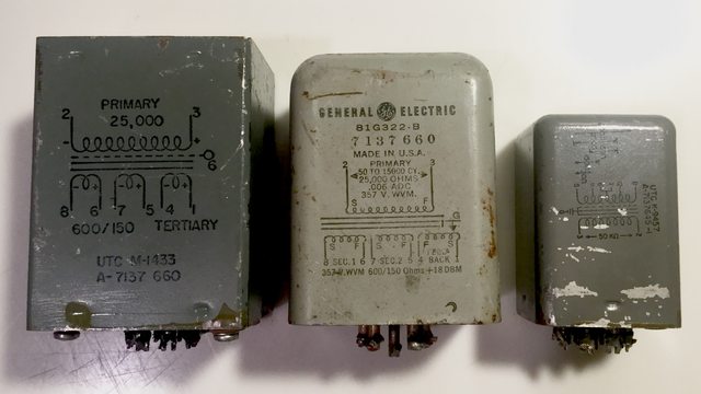
Including the one CJ is excavating, I have 3 of these - one other UTC and what looks by the case to be maybe a Triad. The "triad" has specs screened onto the can. 6mA DC is specified. Not sure why the number differs from the manual. The triad's primary inductance at 100 Hz is only 26H. The frequency reponse is specified on the can as well and matches the figures in the GE catalog. It would seem the UTC iron has considerably better bandwidth than the Triad model. See picture.

I also have 2 inputs for this unit, also UTC. They are a bit bigger than A-type UTC iron, by about 1/4 - 1/3 over again. Side by side picture, below. I'll measure them up and post the specs for them. Could also send one to CJ for analysis, but I've already inundated him with 2 other transformers in this batch I sent.  Maybe down the road, when he whittles through the pile he's got now.

6jXNAqxl.jpg


WKK56Vxl.jpg


BT


Latest posts

Back
Top