strych
New member
Hello, I've just registered here after reading a lot of helpful topics. At the beginning I want to apologize for my possible mistakes, as I'm good at reading in English, but haven't wrote anythig for a long time.
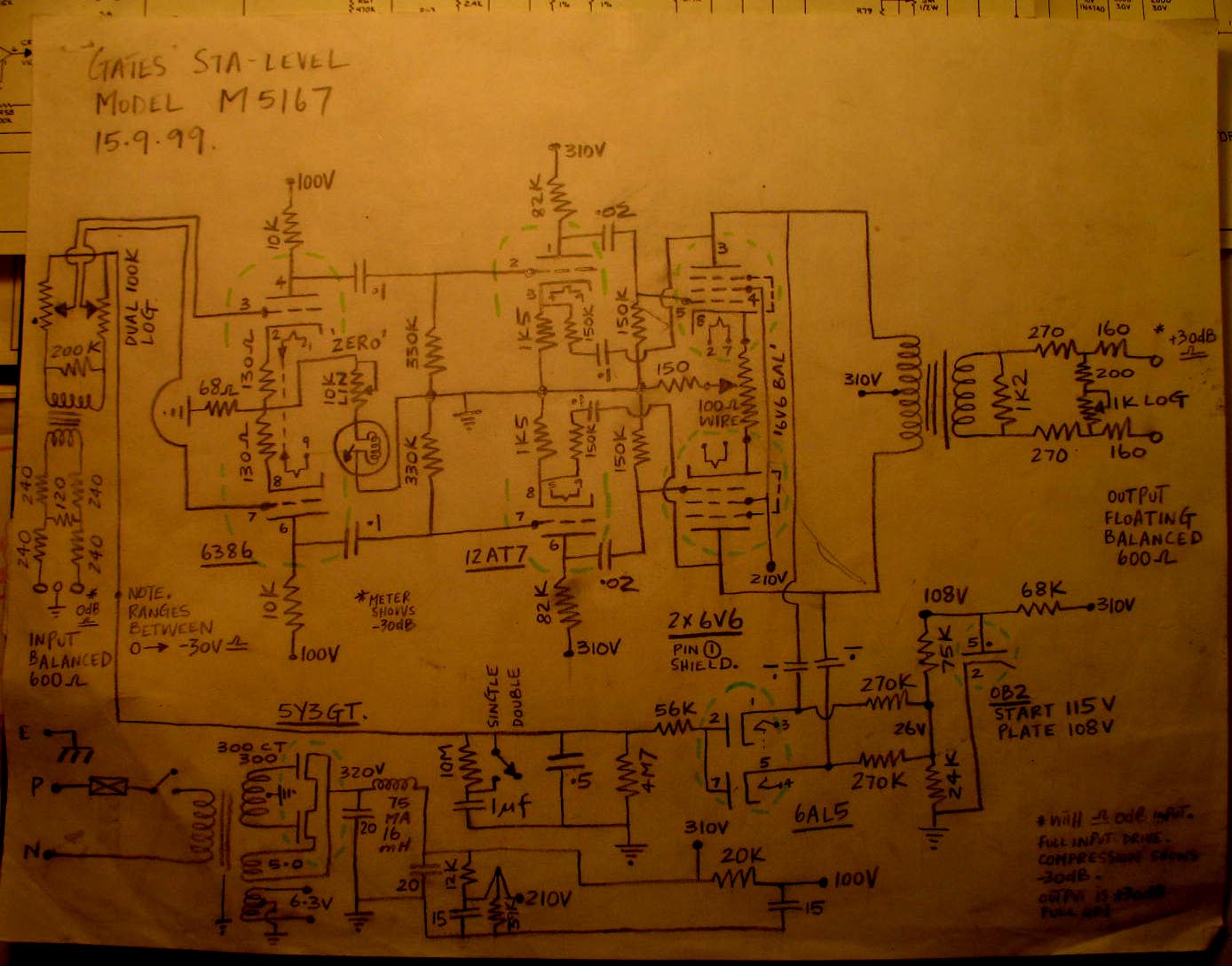
I'm working on vari-mu compressor based on 6386 tubes. It might sounds weird but I have limited budget (when i bought 6386 i didn't know that I will need so many expensive parts to build good vari-mu). I have input and output transformer and want to economize on interstage. So there is most up-to date schematic, there was very much other versions.
http://picasaweb.google.com/lh/photo/91-P9C7283eRbKVS0DTSvXEp_PJAXbbwiYui8xLWXTA?feat=directlink
So now I'll describe my attemps to build working circuit and my considerations. First, I'm aware of limitations of this approach (attack time). Two miliseconds will be good for me, and with cathode followers it is possible I think. I checked rise time at C7 with open feedback loop and it was something near two miliseconds.
I started with simple cirucuit with 6386 in first stage, then 12AX7 with gain about 50 times and unbypassed cathode, and at end cathode follower on ECC88. Cathode follower is the same for all versions just as full wave rectifier. So there were two coupling caps. With this configuration I was not able to get rid of constant low frequency oscillations (from tenth to several Hertz), which were appearing just after warm up and with no input signal. They disappeared only when time constants of coupling caps and grid resistors differed several thousand times (3dB frequency about 1Hz and 15kHz). But such a circuit makes no sense. Now I'll describe how I'm seeing it. First stage is inverting and the same next stage. So, signal feeding rectifier and then filtering cap is in phase with input signal. For high frequencies it doesn't matter, but for very low freqs when ripples on cap are growing, grids of 6386 are supplied by signal which is in phase with input, and it makes positive feedback. I don't know if this is right thinking, though there are circuits with this topology (Altec 436, Collins 356) so what makes them stable?
So I added one more inverting stage and now it was looking something like CCA LA1D. With this topology I hadn't problems with low frequency oscillations after warm up and no input signal. They was appearing when I was switching on generator and the amplitude depended on input signal level, time constants of coupling caps (now three) and grid resistors, and gain of sidechain amp. I've noticed that more gain in sidechain - more problems with oscillations. Sometimes they was appearing with small input levels and dissappearing when input signal was high, and sometimes inversely. I'm talking now about constant oscillations, but there was either fading out ones when input signal level was changing. I read about feedback stability in RDH and there's my conclusions:
1. To make amp with feedback stable, slope on attenuation characteristic when gain is more than one shouldn't be more than 12dB/oct and phase shift shouldn't cross 180 degrees.
2. We have for example three stage amp with 48dB gain and we want 50Hz 3dB frequency. Remebering that slope shouldn't be more than 12dB/oct, only way to achieve that is one stage with narrow bandwitch and two with wider. One coupling cap with grid resistor has slope only 6dB/oct so we must go down eight octaves (or a bit more) to set 3dB freq (about 0.2Hz) of remaining two stages with wider bandwitch to avoid to rapid slope? It would require big caps or big grid resistors.
3. There are step circuits which can help shape phase characteristics but I don't know yet how calculate them to be effective.
It seems to me, that I'm wrong, though CCA LA1D has this topology and is stable with much less differences in time constants of coupling caps.
It's all for now, it's time to sleep. But I will have more questions. I have hope, that my text is understandable")
I'm working on vari-mu compressor based on 6386 tubes. It might sounds weird but I have limited budget (when i bought 6386 i didn't know that I will need so many expensive parts to build good vari-mu). I have input and output transformer and want to economize on interstage. So there is most up-to date schematic, there was very much other versions.
http://picasaweb.google.com/lh/photo/91-P9C7283eRbKVS0DTSvXEp_PJAXbbwiYui8xLWXTA?feat=directlink
So now I'll describe my attemps to build working circuit and my considerations. First, I'm aware of limitations of this approach (attack time). Two miliseconds will be good for me, and with cathode followers it is possible I think. I checked rise time at C7 with open feedback loop and it was something near two miliseconds.
I started with simple cirucuit with 6386 in first stage, then 12AX7 with gain about 50 times and unbypassed cathode, and at end cathode follower on ECC88. Cathode follower is the same for all versions just as full wave rectifier. So there were two coupling caps. With this configuration I was not able to get rid of constant low frequency oscillations (from tenth to several Hertz), which were appearing just after warm up and with no input signal. They disappeared only when time constants of coupling caps and grid resistors differed several thousand times (3dB frequency about 1Hz and 15kHz). But such a circuit makes no sense. Now I'll describe how I'm seeing it. First stage is inverting and the same next stage. So, signal feeding rectifier and then filtering cap is in phase with input signal. For high frequencies it doesn't matter, but for very low freqs when ripples on cap are growing, grids of 6386 are supplied by signal which is in phase with input, and it makes positive feedback. I don't know if this is right thinking, though there are circuits with this topology (Altec 436, Collins 356) so what makes them stable?
So I added one more inverting stage and now it was looking something like CCA LA1D. With this topology I hadn't problems with low frequency oscillations after warm up and no input signal. They was appearing when I was switching on generator and the amplitude depended on input signal level, time constants of coupling caps (now three) and grid resistors, and gain of sidechain amp. I've noticed that more gain in sidechain - more problems with oscillations. Sometimes they was appearing with small input levels and dissappearing when input signal was high, and sometimes inversely. I'm talking now about constant oscillations, but there was either fading out ones when input signal level was changing. I read about feedback stability in RDH and there's my conclusions:
1. To make amp with feedback stable, slope on attenuation characteristic when gain is more than one shouldn't be more than 12dB/oct and phase shift shouldn't cross 180 degrees.
2. We have for example three stage amp with 48dB gain and we want 50Hz 3dB frequency. Remebering that slope shouldn't be more than 12dB/oct, only way to achieve that is one stage with narrow bandwitch and two with wider. One coupling cap with grid resistor has slope only 6dB/oct so we must go down eight octaves (or a bit more) to set 3dB freq (about 0.2Hz) of remaining two stages with wider bandwitch to avoid to rapid slope? It would require big caps or big grid resistors.
3. There are step circuits which can help shape phase characteristics but I don't know yet how calculate them to be effective.
It seems to me, that I'm wrong, though CCA LA1D has this topology and is stable with much less differences in time constants of coupling caps.
It's all for now, it's time to sleep. But I will have more questions. I have hope, that my text is understandable