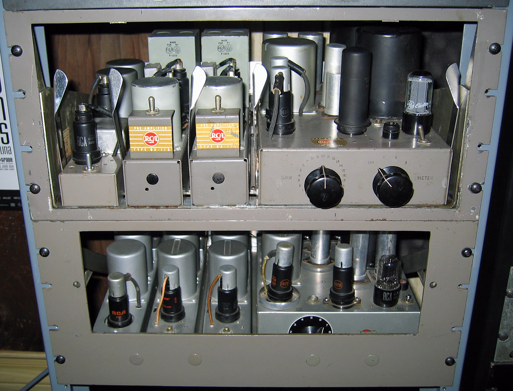
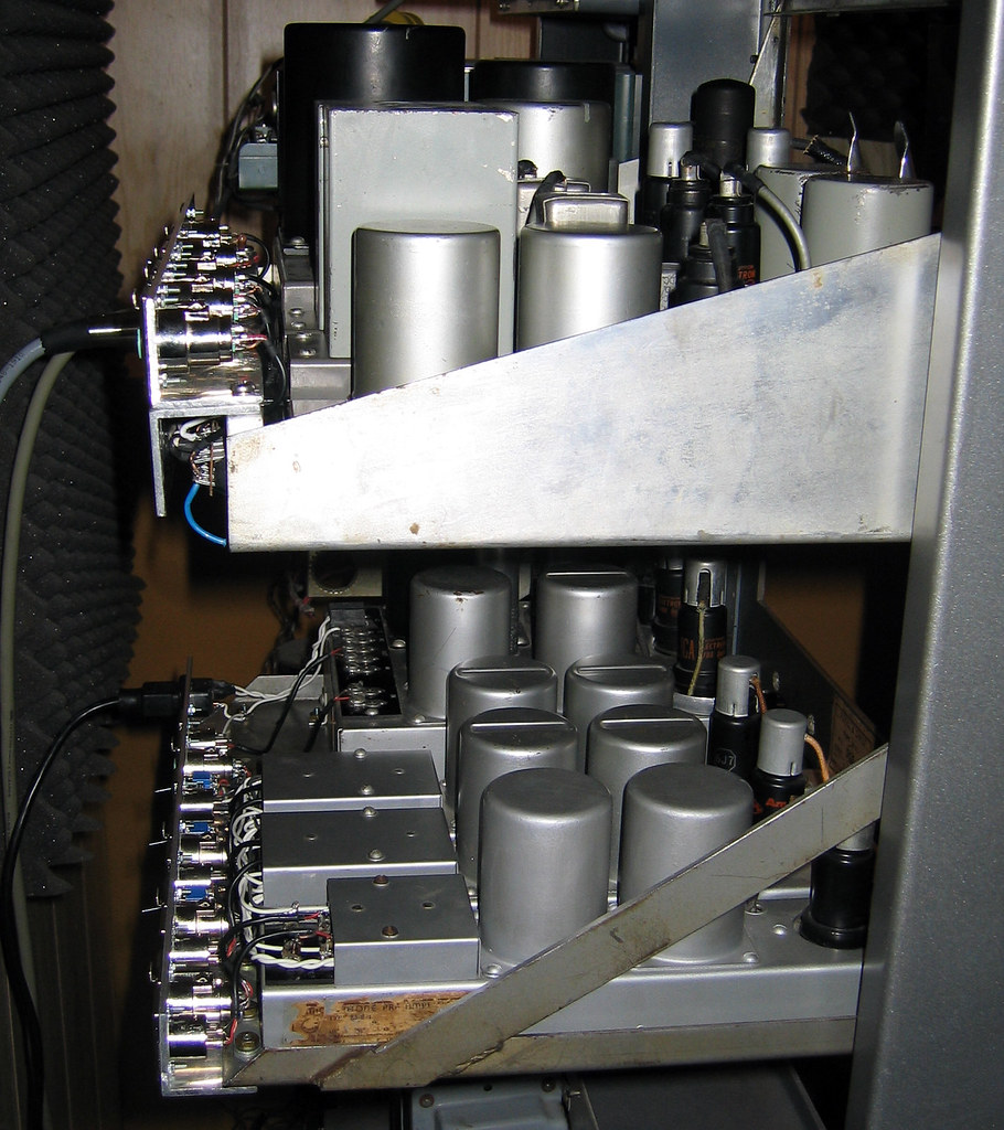
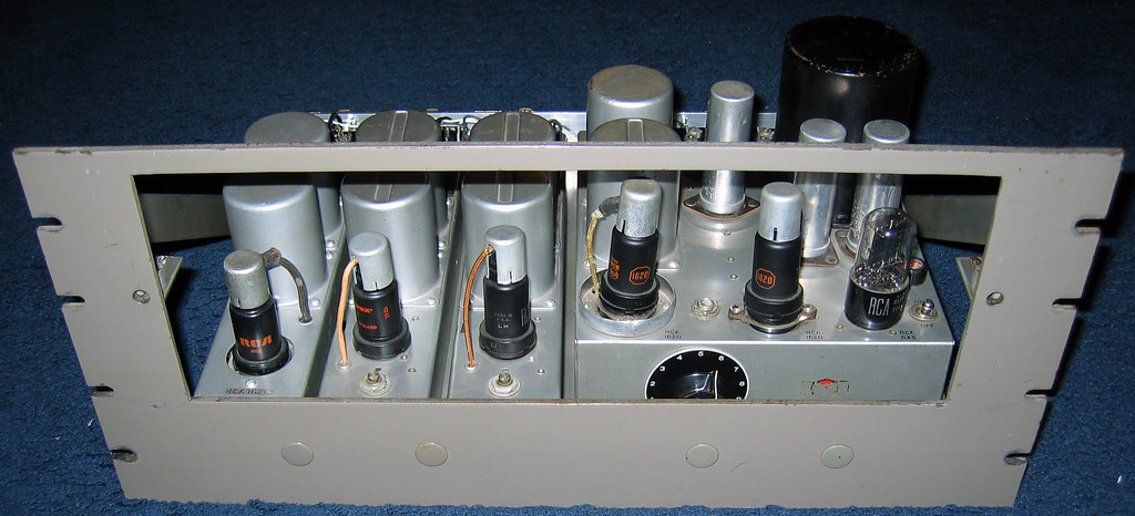
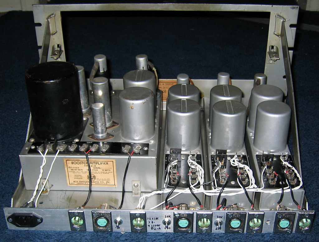
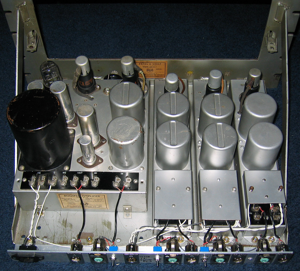
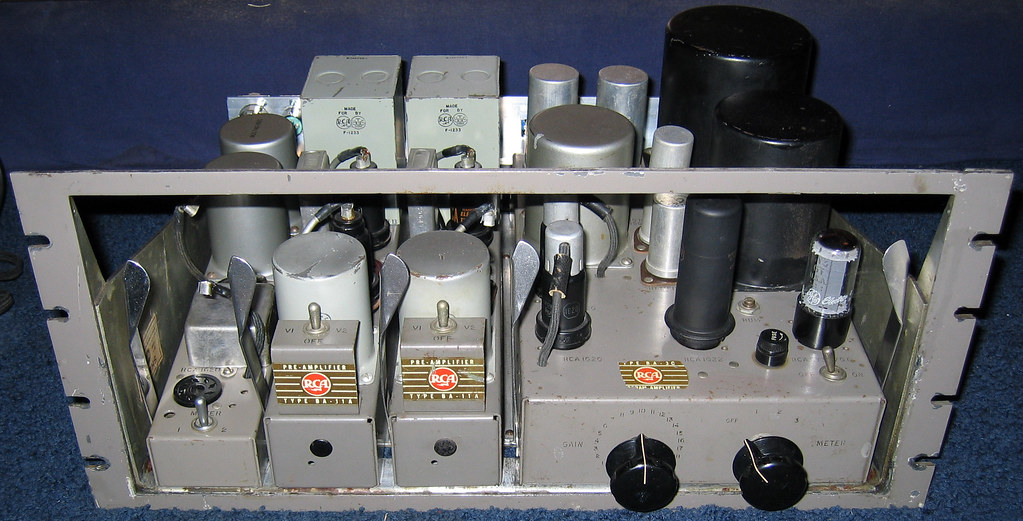
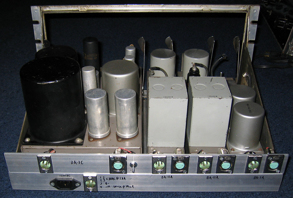
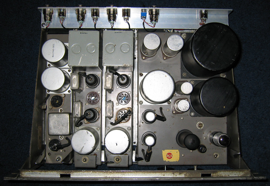
I may add prettier rear labels another time. I have the cosmetic rack face plates, but there are functional issues with installing them, and then having to pull them off constantly. I wish RCA had placed access holes in the faces for use with a full six modules, rather than the four or five hole pattern they chose.
I machined the connector bars out of 1/8" aluminum L bar, rather than hard wiring to a patch bay at a distance. I move pieces around too often to rely on today's judgement call about wire length.
I am currently providing B+ and filament to the non-powered modules with a Heathkit tube regulated bench supply, and am sorting out what will be more permanent.
In many cases the input and sometimes the output transformers had a center tap tied to ground, which can be problematic in modern interfacing. In every case, I have disconnected these center taps and allowed the inputs and outputs to float. It is common for people to try and use one of these preamps today with a condenser mic and a phantom power modification, and many fail to realize that a center tap will shunt the 48VDC to ground through the transformer primary.
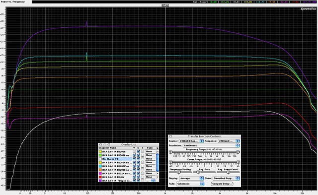
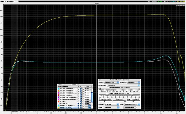
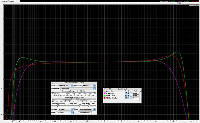
Below are response plots on the BA series rack, after watching real time input and output impedance loading effects, and making some decisions. No resistances replaced, all caps except 1) oil bathtubs, and 2) the pair of mica caps in the BA-3.
My source impedance is roughly 150 ohms here. This is pink noise with a long settling time, 0.7Hz resolution. Straight wire measurement draws a straight line, for comparison.
Input loading varies per unit. The BA-1 top peak grows larger with a 20 dB U pad in front of it, as is commonly needed with microphones. The 3 and the 11 are affected much less.
Output load resistance makes a lot of difference here. The values I've picked make the most sense in my system, where they will sometimes see a 10K load, sometimes a true 600 load.
The BA-1 especially is perfectly flat with a 600 ohm load, this shows a 750 ohm load. This is the only case I've encountered of a preamp showing bottom resonance with so little a difference in loading. This is pentode/pentode 1620 with DC in the output transformer.
The BA-11 is loaded at 1k8, it's top peak is still there a little with 600. This is pentode/triode 1620 with DC in the output transformer, and I once measured about 27 dB of negative feedback in the loop. The second BA-11 matched in measurement.
The BA-3 differs in that a 600 output load takes a lot of treble away. This shows a 1K load, with some additional high frequency boost as described in the manual. A 10K output load with original boost value gave similar response as shown, but I didn't feel great about such a light load on a 6L6 amp. The BA-3 is specified as a line amp, many people these days use it as a low power monitor amp, and hi-fi guys will bypass the input transformer for Hi-Z input. In this case the unit will be used for microphone input, so I disconnected the first of the two ganged pots, now input transformer going to open grid. This is pentode/pentode/beam tetrode 1620/1620/1622 with DC in the output transformer, cathode biased 1622. As secondary evidence, I have another of the input transformer, and it shows a similar sharp treble drop when tested by itself. It is possible the 1622 plate zobel has too much capacitance, or the resistance has dropped. These stability networks tend to be burned up and way out of spec on a lot of broadcast power amps.
The steepness of top and bottom roll-off in the transformers is interesting, and seems quite on purpose. Many other preamps and line amps of the era have much more gradual slopes at the edges. The BA-1 and 11 both have additional small caps in the feedback paths to kill more top end; I have not yet experimented with pulling them out. I also expect to play with the amount of NFB in the 1 and 11, to see where the acceptable limits dwell.
Click this link for the full size plots
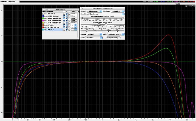
Next is the 80 series rack. This is an 85-B1 preamp, a pair of 85-X isolation amps, and an 87-A. I left all three of these unloaded, so they see as high as 10K on their outputs. I found no obvious frequency changes in any of these amps with varying output loads. Distortion will of course change. Again, these amps will see different output loads depending on the signal path needs of the day, sometimes being 600, so I don't want to double load any amp if unnecessary.
The 85-B1 is a single 1620 triode amp. Identical to the preamps found in the 76 series consoles. There are two plots here, one with direct 150 ohm line source, another with a 20 dB U pad. I suspect my source has fairly weak drive at 150 ohms, and may be the cause of the greater top roll-off. The load may be re-equalizing the source. I suspect a 50 ohm source with a 100-150 ohm build out resistance would give a different plot. The pad exhibits the typical top end boost that an input shunt resistance sometimes causes. With the BA-1, 85-B1, and 87-A, the shunt in the pad was expanded experimentally up to 1K and the top boost remained, so I see no ability to trim it to perfection. All original parts in this one; no electrolytics involved.
The 85-X is a single 1620 pentode amp with plate to grid feedback, feedback variable from about 11 dB to 18 dB. It's input is tapped at 20K and 600 ohms, and was intended primarily for unity gain isolation at medium line levels. At the 20K tap, gain ranges from slightly above to slightly below unity. At 600 ohms you get roughly 12-19 dB gain. This plot is the 600 ohm input at maximum NFB. There's a bit of bumpiness which I found later to be radio interference from a poor ground. I apparently didn't save the 20K plot, but recall that it had a top rise similar to the 85-B1, and more bottom roll-off. The second 85-X matched in measurement mostly, with a little less bottom end. All original parts in these; no electrolytics involved.
The 87-A is two triode 1620's with interstage volume pot. There are two plots here, one with direct 150 ohm line source, another with a 20 dB U pad. Same comments as for the 85-B1 and BA-1. As a side note, these are found in the field with one side of the input transformer grounded, for use as turntable amps. When connected this way, you get a fairly large rise in the high end. New caps in this one, excepting the 330 pfd mica high boost cap in the interstage connection.
Click this link for the full size plots
