voltage doubler power supply schematic

GroupDIY Audio Forum

Help Support GroupDIY Audio Forum:

This site may earn a commission from merchant affiliate links, including eBay, Amazon, and others.

ward

Well-known member
Joined
Jun 4, 2004
Messages
348
Location
Belgium
Can someone check and spot the mistakes in my trace-ing effort
powersupply-1.jpg


This is the voltage doubler psu of my 60's hohner guitaramp.

What could be the intention of the D3. 
It could be wrong connected but why is it there in the first place, 2 diodes is enough for the doubling ?

Thanks.
(edited for mistakes)
(edit: the 15Vac secondary is grounded on one side)
 
> spot the mistakes

Lower-left: "screen grids" is really control grids. C11 C12 surely go to the other ends of R6 R7.

I won't comment on D3. Hohner's approach to design is too wacky for me. I can not guess if you traced wrong or right. I suspect D3 is needed.

What is your real question? Theory, or is it broken?
 
Thanks PRR,

the c11, c12 remark is correct.  I mistraced that.
and thanks for pointing out the control/screen grid mistake.

The real question is actually:
It was never really broken but sounded wrong when overdriven.
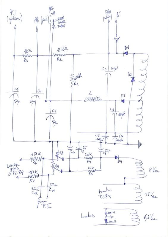
This circuit is what's in there at the moment, after I went in and tried to improve it. ::)
First I replaced the old diodes and the old supply caps.

I scoped it and saw that when overdriven the waveform had nasty spikes.
I narrowed that down to the PI or poweramp.
For a while I believed that the PI was the culprit, I put in a totally new PI, a cathodyne instead of the paraphase.
Why, because I thought the balancing of the paraphase was the problem.
The problem was still there.

When I measured the signal with the power amp out of circuit the PI was giving out a good signal.
With the power amp it's totally wrong, especially with the feedback loop in place
So from then on I was suspecting the power supply is wrong.

It is very likely that I misconnected something right back when I started to replace things in this amp.
As far as I can rely on my scoping skills the voltage on the screen grids is acting weird.

And what I think I understand from the drawn circuit above is the c1, c6, c7, d1, d2 - part.
That looks to me like a voltage doubler from the textbook.
D3 I cannot grasp and is feeding the screen grids, so my question is actually, could it be misconnected.
And how to do it right ?


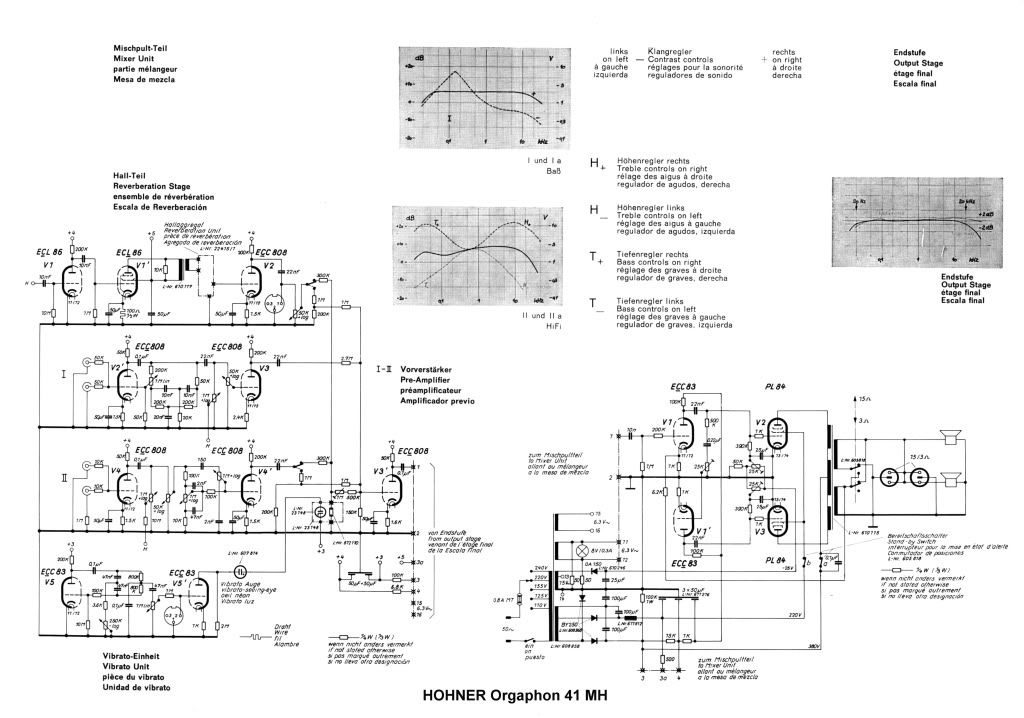
This is how Hohner did it in an other amp from the same series, 
there's not much difference in the PI and PA.
endstufe.jpg

 
Nothing much wrong with a paraphase in mild overload.

> When I measured the signal with the power amp out of circuit the PI was giving out a good signal.
> With the power amp it's totally wrong,
> especially with the feedback loop in place


The driver waveform _must_ go wacko when power tube control grids try to go positive.

The driver waveform gets MUCH more wacko when NFB tells it to try to "correct" the uncorrectable (when the power tube outputs are slammed, hitting their inputs harder won't correct the distortion).

Monitoring the driver, in output overload, with NFB, is just too goofy to make sense of. If it looks wacked, it probably IS working the way it "should".

It is very possible, in this post-post-golden-age, that you don't want NFB in a guitar amp, or only the least little bit to control speaker bass-slap.

> So from then on I was suspecting the power supply is wrong.

Why?

Are the power rails semi-steady from idle to FULL ROAR? I would expect 400V to sag to 350V or thereabouts; 200V would be sick. That's for plates, but a heavy sag on the Screen Grids (say, 200V to 100V) would for-sure sound sad.

The "factory" schematic you posted looks correct. (The bias trims seem wrong, but could be correct.) I can not read the screen-grid dropping resistor (from the two 100u caps). I do not see your "D3". Or any choke.

Without you throwing it on my bench, I'd suggest to try copying the factory connection as exact as possible. CHECK the voltages before you put tubes in (I once screwed-up and was puting 800V where I wanted 400V).

They are not touchstone amps like some Fenders, but they are not bad amps. I'd generally put it back as-built, and be looking for some odd failure which doesn't kill the amp, just makes it nasty.
 
PRR said:
The driver waveform _must_ go wacko when power tube control grids try to go positive.

The driver waveform gets MUCH more wacko when NFB tells it to try to "correct" the uncorrectable (when the power tube outputs are slammed, hitting their inputs harder won't correct the distortion).

Monitoring the driver, in output overload, with NFB, is just too goofy to make sense of. If it looks wacked, it probably IS working the way it "should".
AHA, that's a good lesson, I'll have to check by ear in the future.

PRR said:
It is very possible, in this post-post-golden-age, that you don't want NFB in a guitar amp, or only the least little bit to control speaker bass-slap.
Maybe I have to make it adjustable after I put it back to factory spec.

PRR said:
Are the power rails semi-steady from idle to FULL ROAR? I would expect 400V to sag to 350V or thereabouts; 200V would be sick. That's for plates, but a heavy sag on the Screen Grids (say, 200V to 100V) would for-sure sound sad.
I'll have to check that.
[edit] anode sags from 370V to 340V, grid goes from 212V to 170V. So that should be all right ?

PRR said:
The "factory" schematic you posted looks correct. (The bias trims seem wrong, but could be correct.) I can not read the screen-grid dropping resistor (from the two 100u caps). I do not see your "D3". Or any choke.
What you refer to as the screengrid dropping resistor in the factory schem of the 30MH is the choke.
My amp (possibly a 41MH) has a different power transformer.  My high voltage winding is cut into two sections.

PRR said:
Without you throwing it on my bench, I'd suggest to try copying the factory connection as exact as possible. CHECK the voltages before you put tubes in (I once screwed-up and was puting 800V where I wanted 400V).
I am a bit unsure what to do with my psu,
I don't have no factory schematic of my version (41MH) and my transformer is different.
Off course I should have documented it better before I started replacing things.  :-[ :-[
 
Back
Top