Voltmeter as a VU meter

GroupDIY Audio Forum

Help Support GroupDIY Audio Forum:

This site may earn a commission from merchant affiliate links, including eBay, Amazon, and others.
Since most people don't understand what a VU meter (or even a V-meter!) is, that probably won't matter.

I've done it. well... sorta. I converted a Beede 100µA meter to work in place of a VU meter in my first ever LA2a clone... Here's a pic:

LA2apanel.jpg


In the following image, you can see (if you REALY squint) the diodes and resistor network that I used to make the meter work anything LIKE correctly. It is VITAL to use low-drop diodes like Germanium or Copper-oxide, and the series/parallel combination has to be trimmed a LOT to in any way come close to matching the overall loading/damping characteristic.

LA2a4.jpg


It's a little on the slow side, but it works.

Now... would I do it again? -Never.

Why? -Because it took AGES to get right, the cost in terms of time and parts was more than if I'd have just bought a VU meter on eBay, and it doesn't meet VU spec... even after LOTS of tweaking. -And I hope you can tell from the pictures the amount of dedication and labour which went into making that unit... there was a LOT of care and patience, so it's not a case of laziness.

Buy a VU meter.

A real one.

Keith
 
why germanium diodes? they drop like .3v, why not some nice MODERN schottkys with a drop of .2v?

We've built them better, faster, stronger.. for less than 6 million.. ah screw it, get the schottkys!

:green:
 
[quote author="Svart"]why germanium diodes? they drop like .3v, why not some nice MODERN schottkys with a drop of .2v? [/quote]
Well, I didn't say you HAD to use Germaniums, I just said that you should use LOW DROP diodes, like germanium or copper oxide...

That said, too LITTLE forward-drop is undesirable, for the same reason that too MUCH is, just going the other way... Unless you're going to measure and plot your own scale (now that IS going to be ridiculously expensive!) you'll need the rectifier to take the same toll as the scale that you're using...

In my case I was using a colour-print of an original Teletronix (Beede manufactured) VU meter, and so I had to use diodes with the exact same drop as the originals, in order to make it read correctly across the scale...

-See... -another example of why it takes forever just to save ten bucks!!!

Keith
 
hi all
i'm agree with keith, i made a vu meter with a volt meter, using a super full wave rectifier opamp buffer with trim control, mod the mechanic to have the right ballistic, and so on... a kind of neverending story.
now i'm happy, i know why real vu meter cost more than a volt meter, and i buy only Vu meter within normalized spec
 
Hmmm, I take your point that the effort may not be worth it. I'am really looking for some vintage style meters, which seem to be few and far between. Check out the AM100mV at Webers site for $8.50, they look pretty cool. Also the AM100mA could be good for 1RU panels.

https://taweber.powweb.com/store/meterord.htm

Alternatively anyone know of similar (new) vintage looking VU meters other than the Sifam ones?

Thanks for your advice
Michael
 
wow keith. could you post more hints/info about tweaking those resistors? and maybe a quick schematic? it seems like this might be a good option for higher volume production or even group DIY. you only have to skin the cat once and then the difference in price per unit becomes significant.
 
Check out Rod Elliot's schematic site for this: http://sound.westhost.com/project55.htm

I built a two-channel version for my G9 preamp, and put in the switch to change from VU tp PPM. Works very well with the 100 uA meters I got off ebay. The circuit does require germanium diodes, but they're not too hard to get. Let me know if you're interested - I have an Eagle layout for the two channel version.
 
The question is, are any of the suggested VU buffer circuits likely to get close to making either of the Weber meters work, the larger round one is rated at 100mV FS, the small round one is rated at 100mA FS. Both I think look good for a 2ru and a 1ru box if can be made to work as VU meters or something that reasonably replicates one.

Michael
 
[quote author="mikep"]wow keith. could you post more hints/info about tweaking those resistors? and maybe a quick schematic? it seems like this might be a good option for higher volume production or even group DIY. you only have to skin the cat once and then the difference in price per unit becomes significant.[/quote]
Well, I only found ONE Beede meter of the correct size and shape. The current rating, the impedance and the ballistics would mean that any other meter would need CONPLETELY different values, but it's basically a low-drop bridge rectifier, then a potential divider formed by a series resistor and a shunt resistor to desensitise the over-reading meter. Now that makes the total resistance/impedance too high (compared to the impedance of a typical VU meter) so you have to add a second overall shunt resistance inside the bridge to make it match.

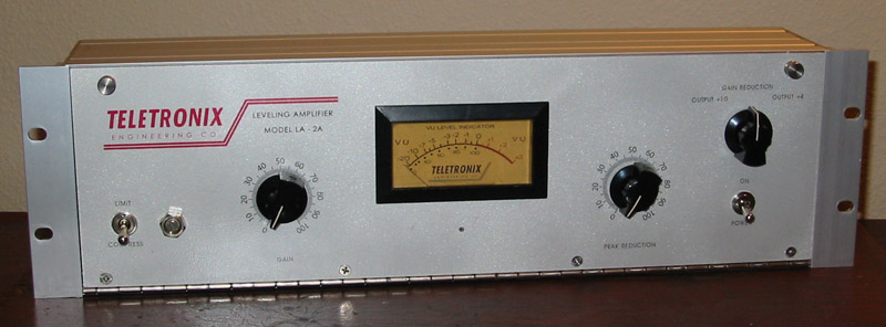
I compared it to meters by Beede (in an original LA2a), Modutec, Sifam, Triplett and a couple of other brands. With the exception of Beede there were several models from each brand, all read slightly differently, so I aimed for the middle of the pack, biased slightly to the Beede for 'sentimental' reasons.

Now, you could just use a lower overall resistance potential divider network, but the shunt part tends to damp the meter movement, slowing it and affecting the overshoot characteristics, making things appear to have been dipped in molasses, so you find values which are too lively then reduce until it looks closer. THEN you add the overall shunt (vital to make the relation ship between the 3.6K series impedance (for +4dB operation in an LA-2a) and the additional 6.8K series resistance (for +10dB operation) otherwise the switch doesn't work right. -Then you notice that the overall shunt is slightly slowing the needle motion, which is why you leave it a little fast before you add the overall shunt. You may have to re-do the potential divider network to adust the ballistics. Then you have to recalculate the overall shunt... rinse and repeat ad frustratum maxima.

Circuit is easy. Parts are cheap. Job is a headache. ...and you simply HAVE to have a few VU meters close at hand to swap-in and compare readings, behaviour and performance.

That meter started out fairly inexpensive, but ended up taking me many hours to get right.

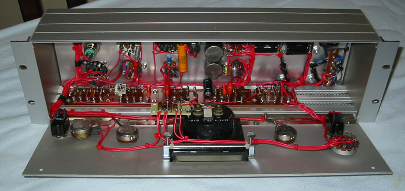
[quote author="mediatechnology"]Sorry for the interruption here but Keith that's the second time I've seen that pic and it's such a beautiful piece of work I had to "right click save as."[/quote]

heheheh... Thanks Wayne; I'm flattered.

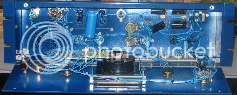
But just in case you think I only work in Red, here's some work from my "blue period":

Insidefront.jpg


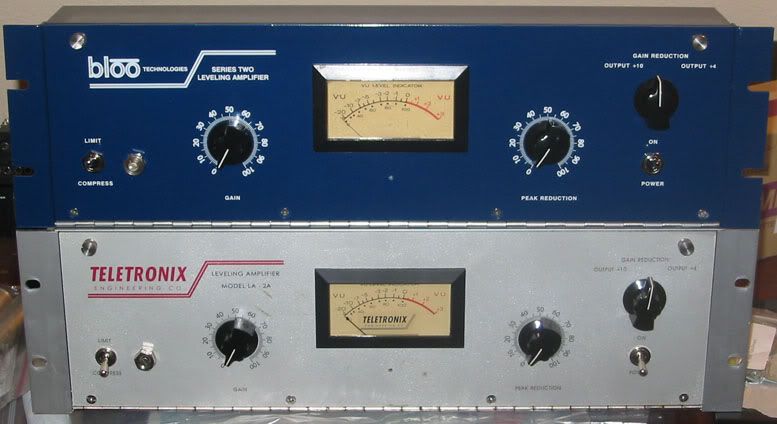
...and here's them both together:
pair.jpg


Yeah.. I get crazy somtimes! :twisted:

Keith
 
Back
Top