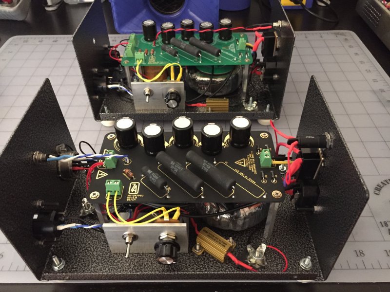
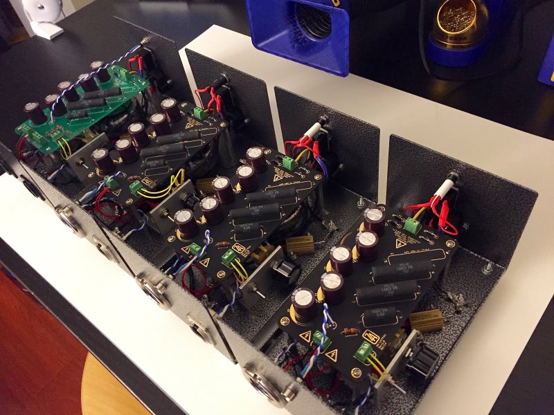
ZAYANCE PCB -NU VAR- NU FED. - STA. -RUDE TUBE.-MKPSU etc....

GroupDIY Audio Forum

Help Support GroupDIY Audio Forum:

This site may earn a commission from merchant affiliate links, including eBay, Amazon, and others.
Category 5 said:
porkyman said:
what are people using for the trim pot?  mouser only sells them by the thousand and they dont have anything similar.

thanks

http://www.mouser.com/Search/ProductDetail.aspx?R=026TB32R102B1A1virtualkey67110000virtualkey774-026TB32R102B1A1

Oh Thanks, i didn't saw that the previous Alpha was only sold by 1000 now.
BOM will be udated.

Thanks Category 5, nice PSU's BTW.


Best,


T.
 
Thanks Zayance.  You might also want to put in there that when using the Triad toroid the resistor values should be 1.5k 1.5k and then 750r for the small one.  With those I get 105V with the pot top-dead-center
 
Category 5 said:
Thanks Zayance.  You might also want to put in there that when using the Triad toroid the resistor values should be 1.5k 1.5k and then 750r for the small one.  With those I get 105V with the pot top-dead-center


are these the test load resistors?... i just ordered the one 2.4k that was on the bom.  could  i add just one 1.5 k/750r or should i scrap the 2.4k all together.

thanks alot for your help cat5, i really appreciate it.
 
No. The test load you ordered is fine.  These are the dropper resistors.  If you use the Triad toroid you need to increase the value of the droppers to get down to 105V.  The choke and pot stay the same but the1k 10w resistors both need to be increased to 1.5k and the 680/330 parallel resistors should be replaced by a 750r 5w resistor.  Then you should get 105V somewhere in the middle of the pot range. 

The Triad toroid has about 40-50V higher output so these changes are to compensate for that. 
 
Category 5 said:
porkyman said:
is there a build thread, or does someone have a pic of a completed unit for the mk47 psu. im having a hard time figuring this one out

large.jpg

Nice builds Cat5! detailed as can be!
Tony Z,  please mark me down for a couple MKU47 boards, if you make the universal board, mark me for 4,

thanx
the other Tony

btw, the black n gold sound better! 8)
 
[/quote]

Nice builds Cat5! detailed as can be!
Tony Z,  please mark me down for a couple MKU47 boards, if you make the universal board, mark me for 4,

thanx
the other Tony

btw, the black n gold sound better! 8)
[/quote]

Thanks TC.  The Black do sound better!  The Blue LEDs also sound better.  ;)

large.jpg
 
ok. ive got pretty much everything bolted down. couple questions i cant make out from the pictures.

1. which direction does the choke hook up, or does it matter? right now ive got the left wire (picture p.o.v.) going to the back hole closests to the caps.  is that the right way?

2. i have no idea where the other end of the heat sink gos. the front ive got connected to ground.

3. the test switch? i might be able to figure that one out but i might as well ask.

4. this is the biggest one. i have no idea how to wire up a 7 pin xlr.  where do 0V/PATTERN/105VDC go? do i run the audio ones straight out of the 7 pin and into the 3pin?

any info would be great, or if i could get a picture under the hood of the green board, that would be great too.  cant thank you enough.
 
porkyman said:
ok. ive got pretty much everything bolted down. couple questions i cant make out from the pictures.

1. which direction does the choke hook up, or does it matter? right now ive got the left wire (picture p.o.v.) going to the back hole closests to the caps.  is that the right way?

2. i have no idea where the other end of the heat sink gos. the front ive got connected to ground.

3. the test switch? i might be able to figure that one out but i might as well ask.

4. this is the biggest one. i have no idea how to wire up a 7 pin xlr.  where do 0V/PATTERN/105VDC go? do i run the audio ones straight out of the 7 pin and into the 3pin?

any info would be great, or if i could get a picture under the hood of the green board, that would be great too.  cant thank you enough.

1 - The choke is not a polarized part so it does not matter which way you hook it up.

2 - If you're talking about the dummy load resistor, one side goes to ground, the other goes to B+ by way of the small switch.  This is so you can easily switch the resistor into the circuit to provide a draw on the B+ line similar to that of the mic.  Usually the mic is a slightly larger load so if you dial in 105 with the dummy load you'll start off below that when you connect the mic.  Don't connect the mic with the dummy load engaged.

3 - One wire connects to the B+ terminal while the other connects to the dummy load. 

4 - You wire it to match the mic.  I have been using this layout.  Pin 1 - Audio +, Pin 2 Audio -, Pin 3, 4, 7 Ground, Pin 5 - B+, Pin 6 - Pattern.  Don't follow this guideline unless your mic is wired that way but it's generally wise to use pin 7 (the center pin) as ground.  Double check the labeling on the connector when soldering.  It's easy to get confused and wire the connector backwards if you're not careful, which would short B+ to the Pattern selection through the output transformer in my example above.  That wouldn't be great.
 
and always, always, always, always, always, always, always, always, always, always, always, always, always, always, always, always, always, always, always, always, always, always, always, always, always, always, always, always, turn OFF the psu and let it drain before plugging the mic in... or zzzzzZZZZZ! :eek:
 
thanks again Category5. no way i could have gotten this far without your help.

got it working and calibrated with test load. havent tried it with the mic yet.

"Don't connect the mic with the dummy load engaged." - can i just disconnect the test load now from the 105vdc slot and only have mic line connected?

a million thank yous.
 
porkyman said:
thanks again Category5. no way i could have gotten this far without your help.

got it working and calibrated with test load. havent tried it with the mic yet.

"Don't connect the mic with the dummy load engaged." - can i just disconnect the test load now from the 105vdc slot and only have mic line connected?


a million thank yous.

No sweat.  You can disconnect the load if you like but the switch is there for that.  Just disengage and you're ready to go. 

I recommend readjusting the voltage when you change tubes.  Different sets of tubes have different current draw and your voltage may go up or down when swapping them.  Enough to warrant a re-check. 

The voltage will fluctuate some with the mic connected.  This is normal.
 
Hello!
Looking forward to building 2 PSU's for the MK-U47. Could you be so kind to put me on the list for 2 pcb's?
Ordered 2 MK-U47's today and they are on their way....
;D
Cheers,
Marcel
 
Back
Top