gyraf g7 with rk 67 capsule

GroupDIY Audio Forum

Help Support GroupDIY Audio Forum:

This site may earn a commission from merchant affiliate links, including eBay, Amazon, and others.

Chrys

Well-known member
Joined
Sep 18, 2013
Messages
53
Location
Italy
Hello guys....
just wanna build a pair of g7 mics and I was thinking to use rk67 capsule from microphone parts
Does anyone try that capsule with this mic?
I tried to find some info about but ...nothing....also on the mic parts site I didn' find info about the voltage of the capsule
Do you guys think I have to make some mod in the circuit?
Thanks a lot

Chrys
 
Disclaimer- All this info comes from internet readings

AFAIK the K67 capsule is emphasized in the top end to be de-emphasized through negative feedback in the head amp. What this means is capsules such as the ck12, m7 and k47, which have flatter responses, are better for the g7 circuit unless you want a very bright mic.

Again, the disclaimer
 
Oh ok Thank you....seems I have to give up this Way. ..
maybe in batter to go to rk47 or rk 12

thankx :)
 
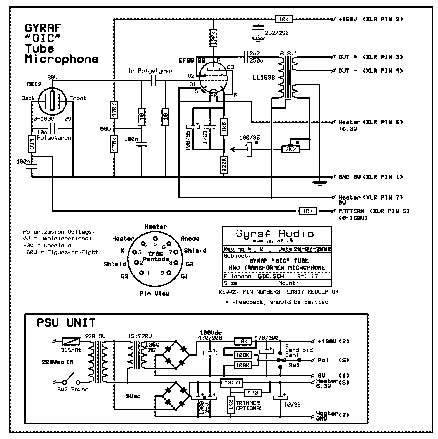
The G7 is prepared for a K67, too.
You have to connect the feedback network of the transformer.
If I remember correctly I discoverd a small failure on the boards: The feedback winding of the tranny needs to be phase reversed. Otherwise you'll get the strange behaviour Jakob was talking about in the past.

I myself have two G7s here equipped with original Neumann K67 - those are simply stunnig and quite often our goto mic...
 
chefducuisine said:
The G7 is prepared for a K67, too.
You have to connect the feedback network of the transformer.
If I remember correctly I discoverd a small failure on the boards: The feedback winding of the tranny needs to be phase reversed. Otherwise you'll get the strange behaviour Jakob was talking about in the past.


Care to elaborate on this?


EEMO1 said:
chefducuisine said:
The G7 is prepared for a K67, too.
You have to connect the feedback network of the transformer.
If I remember correctly I discoverd a small failure on the boards: The feedback winding of the tranny needs to be phase reversed. Otherwise you'll get the strange behaviour Jakob was talking about in the past.


Care to elaborate on this?
On the schematic, there is a split secondary on the transformer and a "floating" feedback connection into the cathode circuit indicated by an arrow. For use with a pre-emphasised K67 capsule, you should connect this part of the circuit.

gic_s.gif
 
Hello,
I think that if You use the given Values from the Schematics You get a Fullrange Feedback, that means that all Frequencys are damped in the same Manner,.
So if You want to tame down the high Frequency Rise from a K 67 it would be good to have a Frequency related Feedback.. With the 2 k2 Poty You select the Amount of the negative Feedback that goes  back into the Cathode, the 100uF Capitor is  Part of a  Highpassfilter. My Question is , if f cut ( - 3 dB Point ) =1/( 2 pi *R* C ) of this HP First Order ( 6 dB ) ,  what is the R in this Formular ? Is it the Impedance of the Secondary from the Outputtranny , in this Case 600 Ohm or the 1,6 k Ohm Cathoderesistor  ? I think it s the ac Resistance of the Outputtranny. It would be Great if Somebody could confirm  or correct this and could Explain .
Thank You very much,
Greatings, Lothar.
 
Back
Top