Onward.
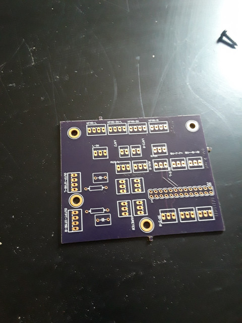
I have designed a small 'utility' board that acts like a junction for the master section, the aux return and the Left and Right bus, I am not sure about the o) and grounding. Should I use a ground plane? Should this be where I connect 0v to case or should I do it at the main out xlr's? The Left and Right bus and 0v leave the backplane to this utility board and then onto the input xfmr and ln72 boards. The EA-1166 doesn't have a ground and upon leaving the EZLN I have a shield out so I just ran a third wire from the 'Shield" out tightly around + and - to the utility board. I think the rest of the board is self explanatory but I would love some feedback or suggestions.


")