


soapfoot
Well-known member
I received some help on this forum awhile back designing a power supply for a mic. My original intent was to use an EF12 tube, but after receiving some counsel from smart folks, I decided to abandon that route and go instead for an EF800 tube. Some told me that the EF12 would work best with a plate voltage and plate loading that was higher than what was found in the U47. Whether this was true or just one person's opinion, I decided to go the easy route and use an EF800 instead.
Well the power supply has been completed, and the mic build is in progress. In case anyone is interested, I'm going to post some photos of my progress.
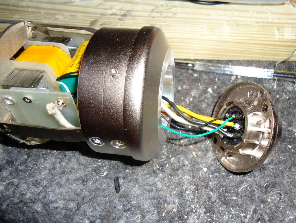
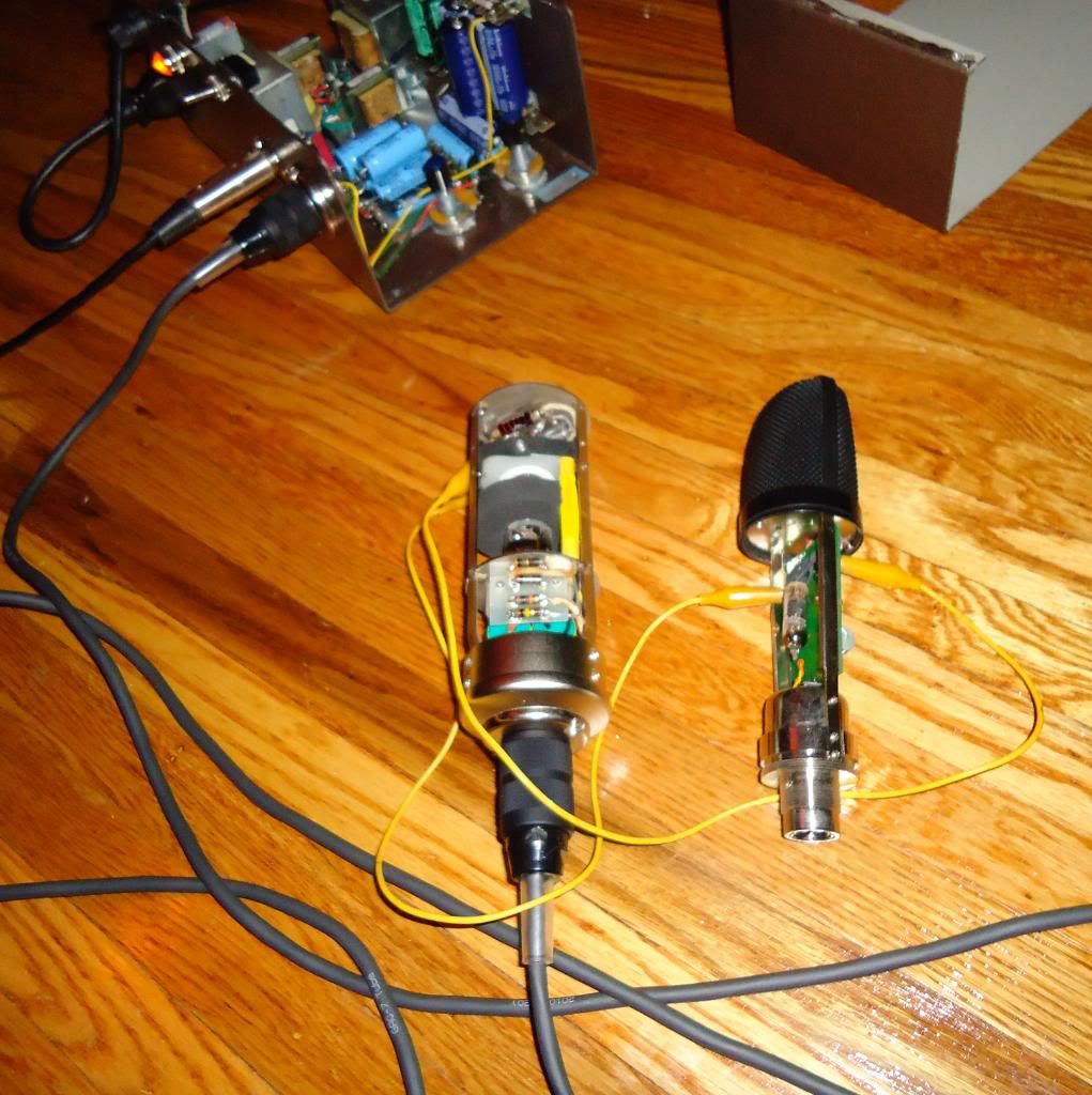
Just to bring us up to speed on the PSU (which was chronicled to an extent on the long-buried and bloated original help thread), here's how my power supply and multi-pin cable with Binder connectors came out:
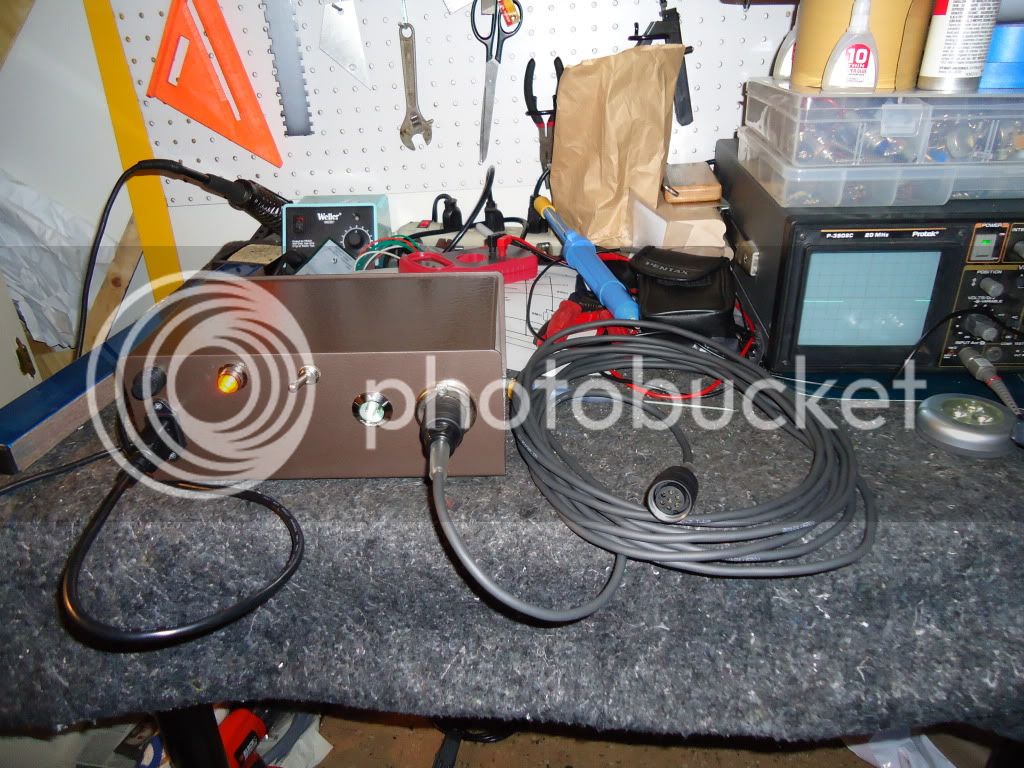
The PSU scopes nice and quiet, so I'm optimistic. Voltages are adjustable. Dual-choke design on the B+ side should make it nice and quiet.
I ordered the TAB-Funkenwerk U47 kit mainly because I really wanted to use the AMI/TAB transformer. It has a high reputation for being very good. That kit isn't a 'true' U47 kit... there are some things about it that are modern touches, namely a plastic capsule deck and no real provision for on-board pattern selection (I think the assumption is that you will do remote pattern selection at the PSU). I wanted to go closer to simple/original, so I bought parts from Telefunken-Elektroacustic, hoping to make them fit.
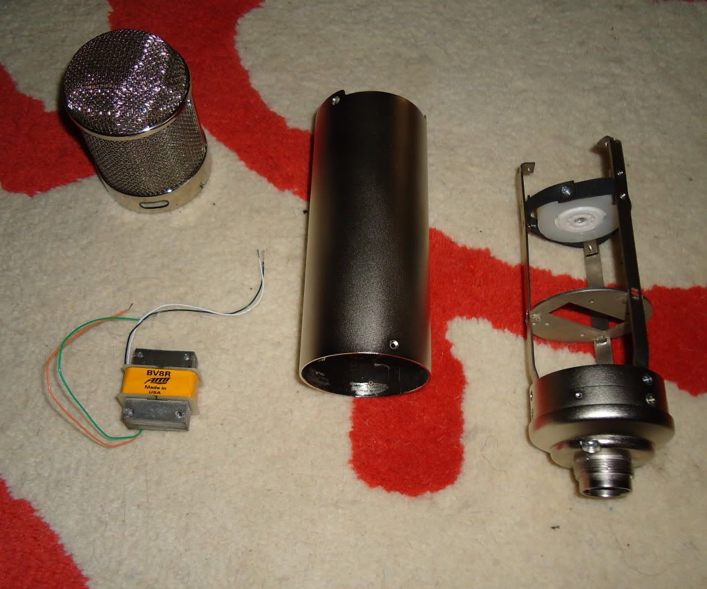
Well, that didn't work out so well. While both companies maintained that their parts were 'vintage correct,' they did not fit together. The capsule deck on the headbasket was a minor screw/hole alignment issue that was relatively easily remedied, however the top plate on the mic body itself was a bigger issue-- the alignment pin from the capsule deck was interfering with the top, flat portion of the AMI body's side rails. Fortunately, AMI offered to help me, so I sent everything to them--truly excellent service-after-sale. When I received the parts back, they had shortened the top portion of their siderails and finessed the screw holes on the T-Funk parts. I will offer no comment on whether either or both companies' parts are truly vintage-correct, because I can't say. But with AMI's help, I did get them to work together. So I'm a relatively happy customer now.
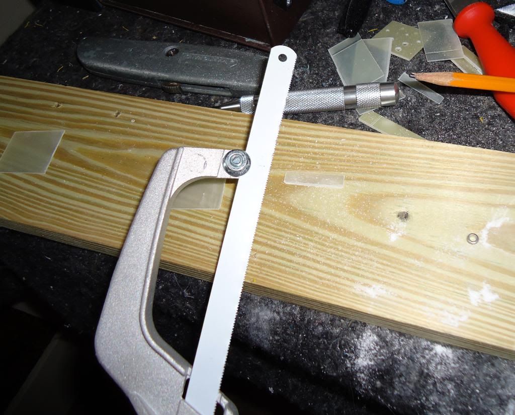
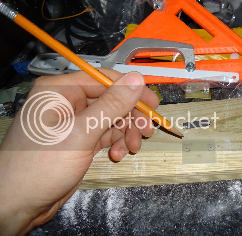
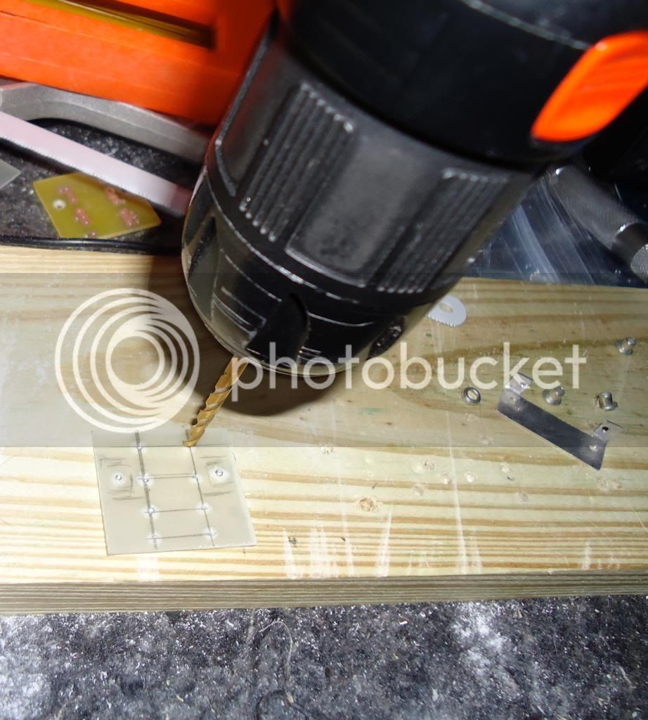
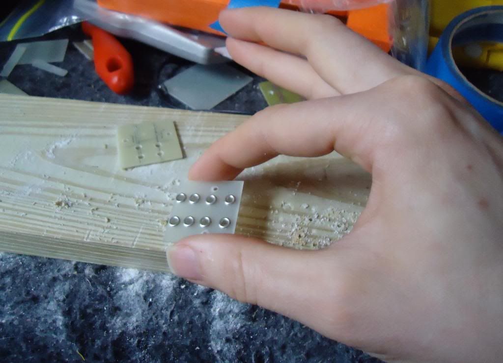
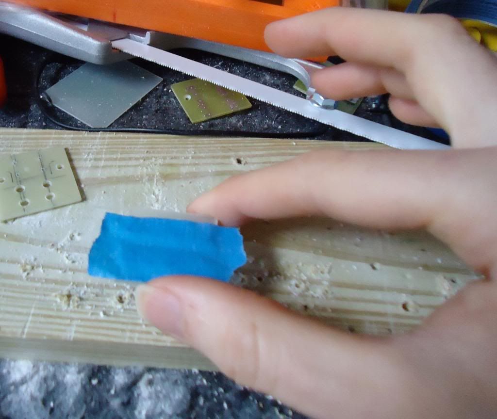
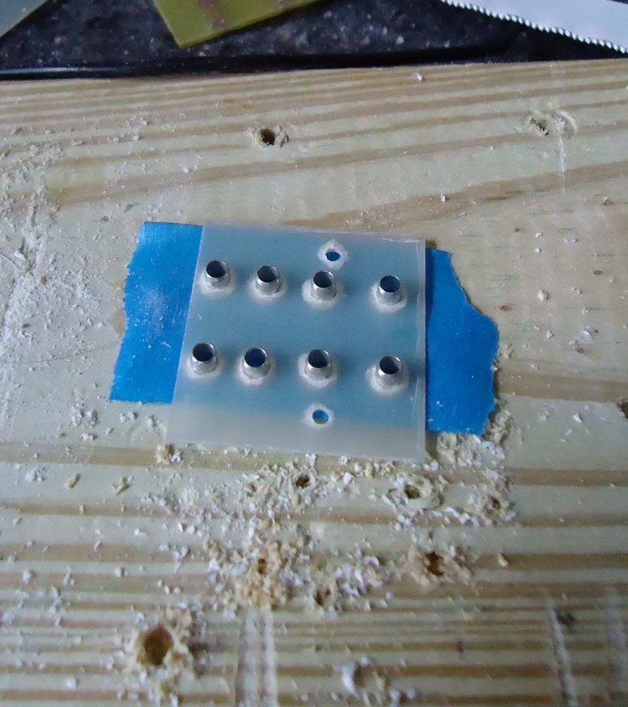
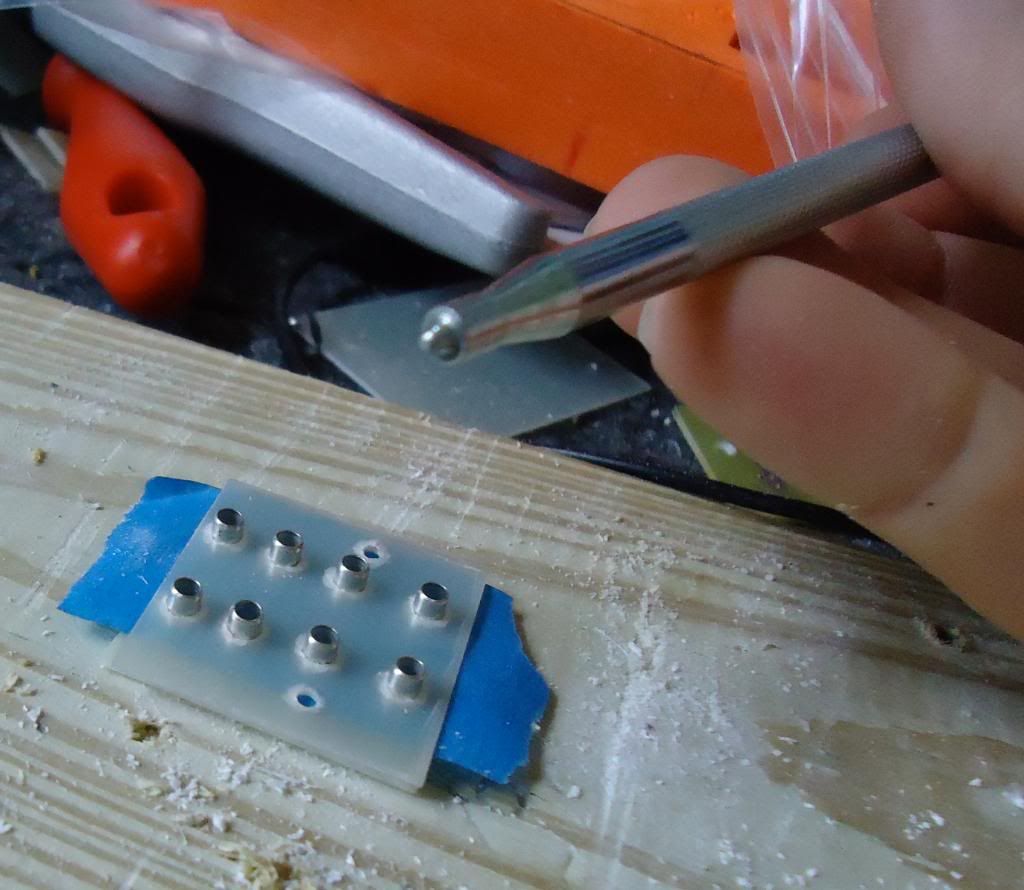
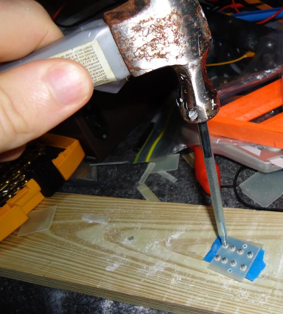
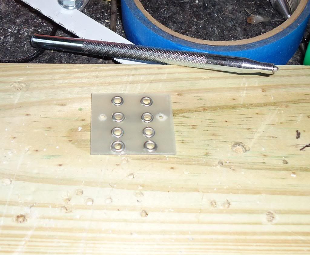
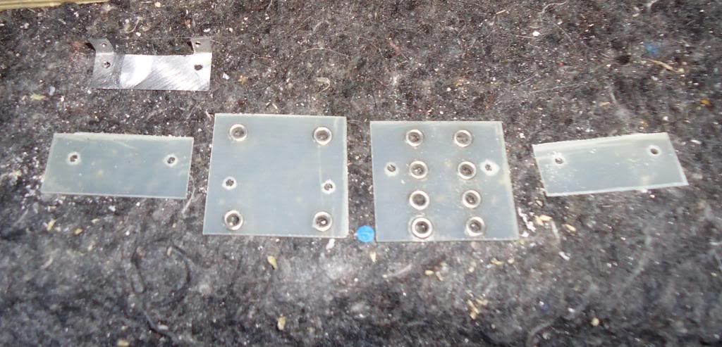
My other quibble with the AMI stuff is that the printed circuit boards provided with the kit didn't really have a look and feel I personally preferred. They seemed a bit like board that were (or could be) home-etched, and a board layout was not provided with them-- so I decided I would make my own eyelet boards with parts from turretboards.com. If this doesn't work out as well as I hope, I will look to other vendors to find a cleaner, more original solution. I had one go 'round already, and while they came out OK, I'd like to try one more time for a cleaner visual look (better alignment on the eyelets). So I ordered more parts that should be here later in the week.
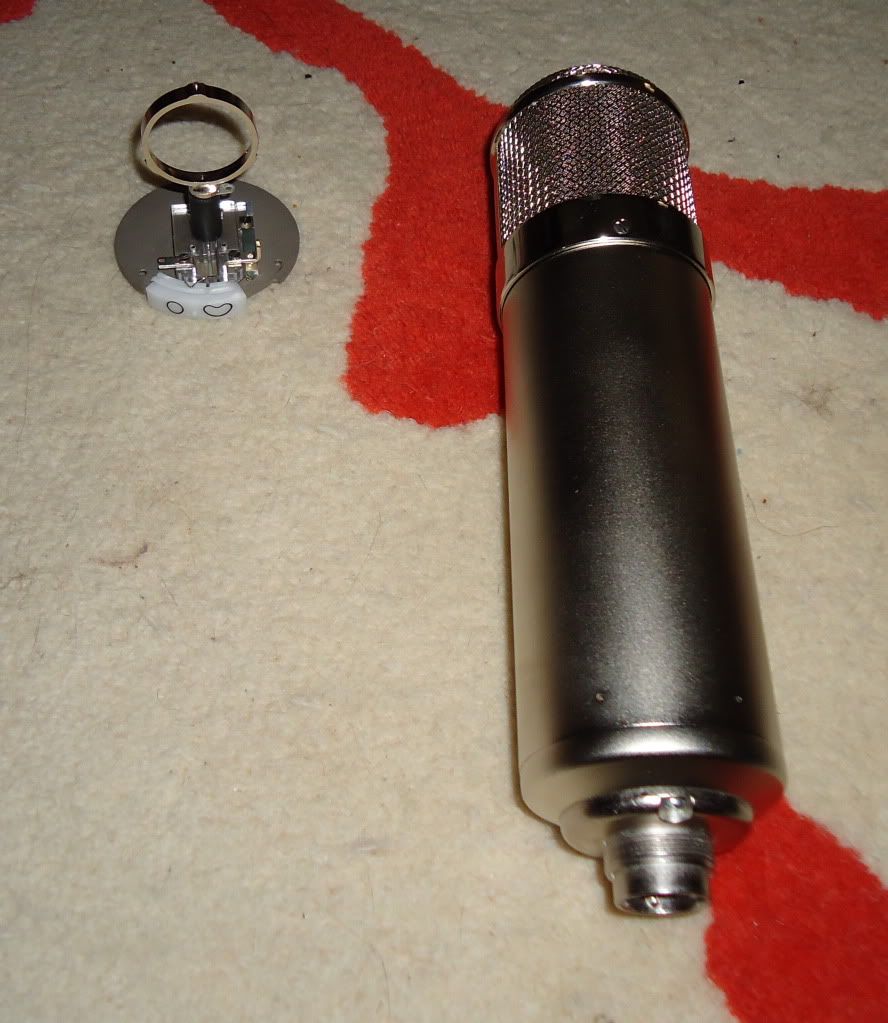
With that on ice, I decided to get to work on the crucial high-impedance portion of the mic circuitry-- the part between the capsule and the tube.
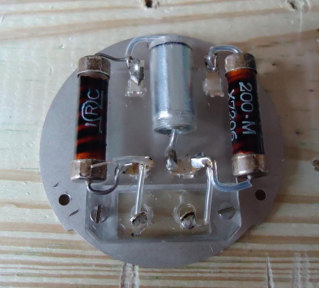
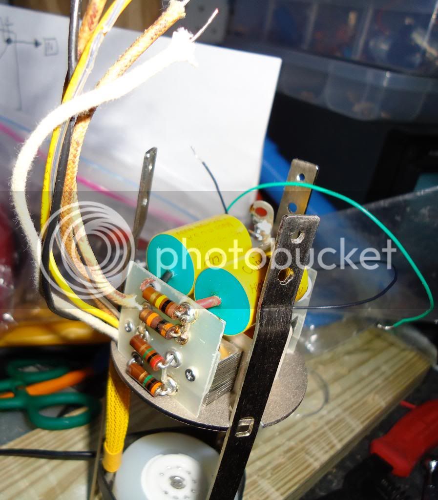
For parts here, the .01 capacitor attached to the backplate is a NOS polystyrene cap selected to be exactly .01µf. For the grid resistor and capsule polarization resistor, the original schematic listed either 60M and 100M, or 100M for both. Oliver Archut's "alt tube" EF800 schematic lists 1G for both-- he stated at least once on Klaus's forum that increasing both all the way up to 1G improves performance. I've seen other opinions to the contrary, naturally (everyone seems to have their own opinion). I decided to 'split the difference' with a couple of NOS TRW hi-meg 200M resistors. This is at least double the original spec, so it should work great. I bought a lot of 10 and wanted to select the highest-resistance ones, but I don't have a megohmmeter. What I did was to parallel them with a 2M resistor, and measure the parallel pair. A couple of them seemed to make the resistance read slightly higher, so I figured these were the highest ones. I chose those.
I also purchased some solid-core 24AWG pure silver teflon-insulated wire. I just bought a couple of feet, so it wasn't that expensive. I used/will use this for all signal-carrying wires in the mic (mainly just because I have/will have enough left over), but I bought it because I wanted to use that in this critical section. Maybe it matters, maybe it doesn't... but it was only a few bucks and I'm only building one. Why not go 'first class.'
I also have some teflon sleeving that I slipped over component leads.
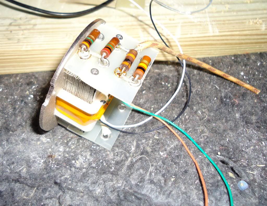
Then I added lengths of wire to the top plate for capsule polarization and master ground. I also added a strategically-positioned 29 ohm resistor which is a part of the filament/bias circuit. This is kind of like building a ship in a bottle, so everything had to be mocked up, carefully trimmed, etc. There's even a tiny piece of teflon sleeving on the short lead of that 29 ohm resistor. Besides the hi-meg resistors, all other resistors in this mic will be NOS Allen-Bradley carbon comps. I just like these resistors, and I have a good source for them, so I figured why not use my favorite resistor (others will prefer other types). I bought several of each value and selected ones that were very close in tolerance-- typically I was able to get within 1% and 2% of the stated value.
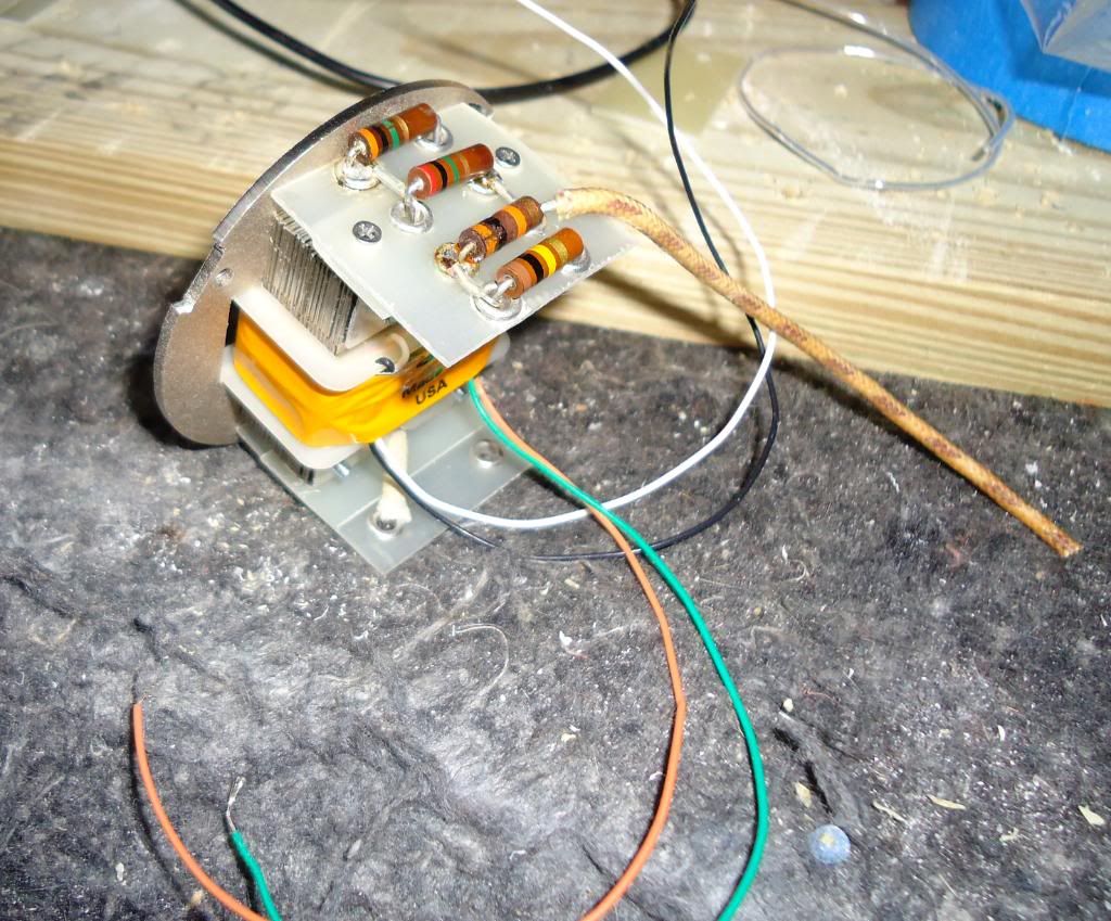
For the ground wire, I used lacquered cloth-insulated wire typical of the period-- no functional reason, just looks. For capsule polarization, I used some cool lacquered cotton-over-PVC insulated wire that was harvested long ago from a junked old Philco tuner/radio from the 1950s. Again, no reason other than looks. For the higher-current heater wires, I used modern PVC-insuated wire. Now we're ready to try and put this top plate on the mic, and make the last 2 finicky solder connections in this area.
A 100 ohm resistor for the filament/bias supply had to find a home. It fit on the tube socket itself after trimming a bit of metal from the center of the ceramic tube socket (it was on the socket, I'd guess, for a ground connection that isn't used for the EF800). Here you'll see also the 22 ga PVC-insulated stranded copper wire used for the higher-current (~275mA) filament circuit.
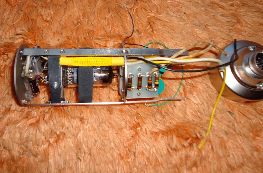
That's done! Now time to slip some TechFlex™ expandable nylon braiding over all the wires to make it look neat. I used yellow because that's consistent with what I've seen in old Neumanns. I also used some yellow heat-shrink tubing to make it all secure. First on the top...
...then on the bottom.
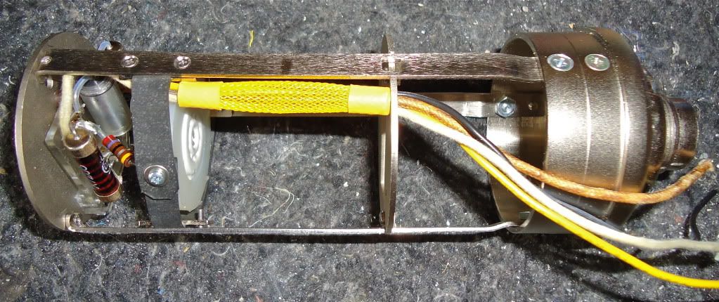
...then apply heat to shrink the heat-shrink, and stuff everything through the transformer plate. In order to get this big mess of wires through the transformer plate, I had to enlarge the hole slightly with some needle files.
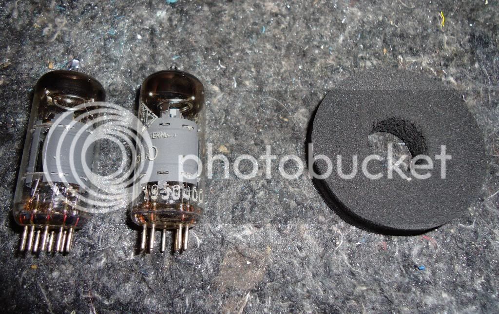
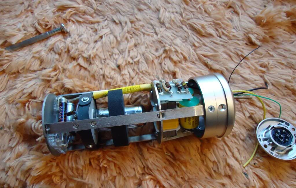
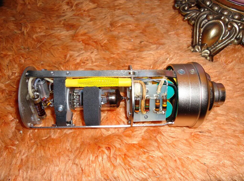
I was going to put the tube in last, as that seems common sense. But since I didn't have my eyelet board making materials yet, and since building 'top down' kind of makes sense anyway (and because I could always remove it later if I had to), I decided to install the EF800 tube. Here I have two NOS Telefunken tubes from which to select the quietest/best one. I also have a donut-shaped foam tube damper purchased from eBay. I hadn't seen this style before, but it reminded me of the kind they put on the VF14 in the old Neumanns, and it was a perfect diameter, so I grabbed it.
installed...
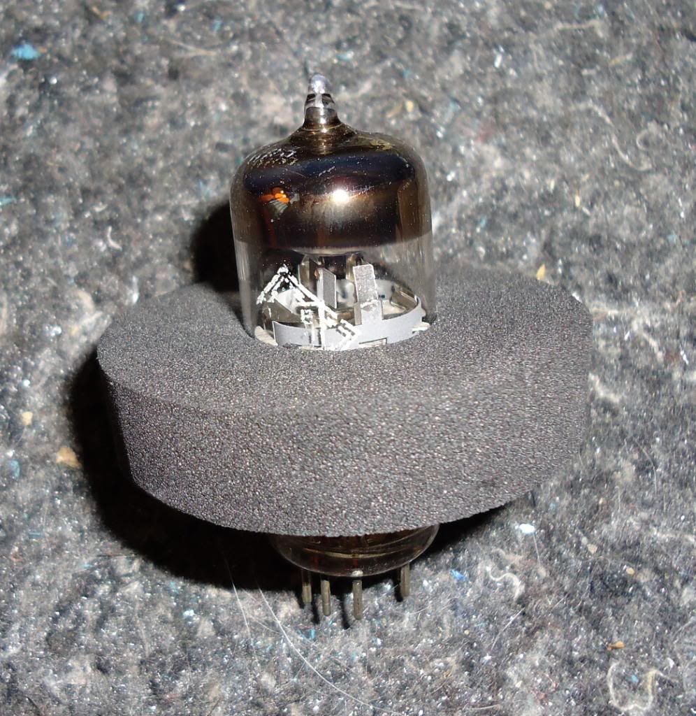
It's certainly doing something. The fit is very snug, and rapping the tube's envelope with a fingernail now gives a dull 'clunk' as opposed to a 'ping.' A test-fit reveals two issues. First is that my sleeved bundle of wires won't clear the foam donut. This is easily remedied with a few well-placed strokes of a round file.
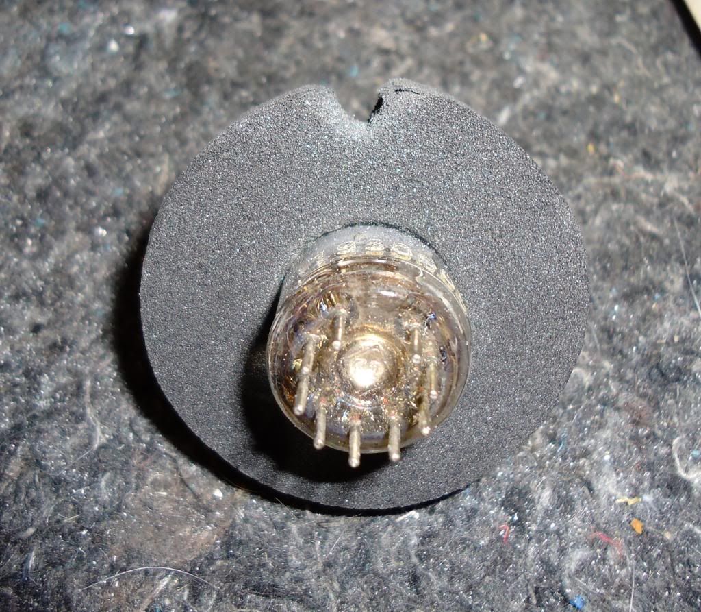
The second issue is that the contacts in the tube socket were so tight that I couldn't insert the tube. This is the opposite problem one usually runs into with tube gear-- usually the sockets become 'sprung' over time and require re-tensioning. In this case, I had to de-tension them slightly. I used a sharp pick to ream them out just a little so that the tube could be massaged in. (sorry for the bad photo)
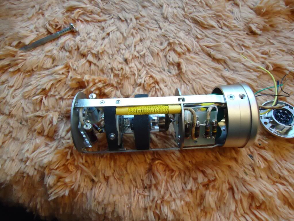
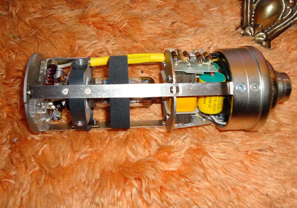
pretty nice fit now.
After soldering the components to the top plate and before mating to the mic body and tube socket, I cleaned all flux residue from the acrylic decking (and thoroughly cleaned the resistor and capacitor bodies themselves). After everything was all together, I took another opportunity to clean any fingerprints, etc. from this area of the mic.
My eyelet board materials should be here soon, and I'll be able to get down to the business of putting together the lower portion of the mic. I had originally purchased vintage Sprague Vitamin Q oil-filled capacitors to use, but these proved to be far too large to fit in the microphone. I increased the coupling cap size to 1µf (from .47) as per Oliver's schematic and the advice of others (to make the response go closer to 20 Hz, instead of rolling off around 40). I ended up going with Audience Auricaps, since they would physically fit and have a decent reputation for tube circuits (without being overly large and/or expensive). I realize the coupling cap is far more critical for audio, but I admit to liking the visual symmetry of having two identical caps under the transformer. Means nothing to anyone but me, and I'm OK with that.
I have ordered a Thiersch STW-7 Blue Line PVC M7-style capsule. It will be about a month before that arrives, and by then I should be ready to complete my microphone and see if it sounds as good as I hope it will.
Well the power supply has been completed, and the mic build is in progress. In case anyone is interested, I'm going to post some photos of my progress.
Just to bring us up to speed on the PSU (which was chronicled to an extent on the long-buried and bloated original help thread), here's how my power supply and multi-pin cable with Binder connectors came out:
The PSU scopes nice and quiet, so I'm optimistic. Voltages are adjustable. Dual-choke design on the B+ side should make it nice and quiet.
I ordered the TAB-Funkenwerk U47 kit mainly because I really wanted to use the AMI/TAB transformer. It has a high reputation for being very good. That kit isn't a 'true' U47 kit... there are some things about it that are modern touches, namely a plastic capsule deck and no real provision for on-board pattern selection (I think the assumption is that you will do remote pattern selection at the PSU). I wanted to go closer to simple/original, so I bought parts from Telefunken-Elektroacustic, hoping to make them fit.
Well, that didn't work out so well. While both companies maintained that their parts were 'vintage correct,' they did not fit together. The capsule deck on the headbasket was a minor screw/hole alignment issue that was relatively easily remedied, however the top plate on the mic body itself was a bigger issue-- the alignment pin from the capsule deck was interfering with the top, flat portion of the AMI body's side rails. Fortunately, AMI offered to help me, so I sent everything to them--truly excellent service-after-sale. When I received the parts back, they had shortened the top portion of their siderails and finessed the screw holes on the T-Funk parts. I will offer no comment on whether either or both companies' parts are truly vintage-correct, because I can't say. But with AMI's help, I did get them to work together. So I'm a relatively happy customer now.
My other quibble with the AMI stuff is that the printed circuit boards provided with the kit didn't really have a look and feel I personally preferred. They seemed a bit like board that were (or could be) home-etched, and a board layout was not provided with them-- so I decided I would make my own eyelet boards with parts from turretboards.com. If this doesn't work out as well as I hope, I will look to other vendors to find a cleaner, more original solution. I had one go 'round already, and while they came out OK, I'd like to try one more time for a cleaner visual look (better alignment on the eyelets). So I ordered more parts that should be here later in the week.
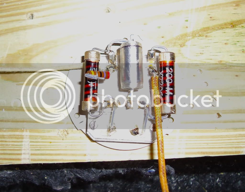
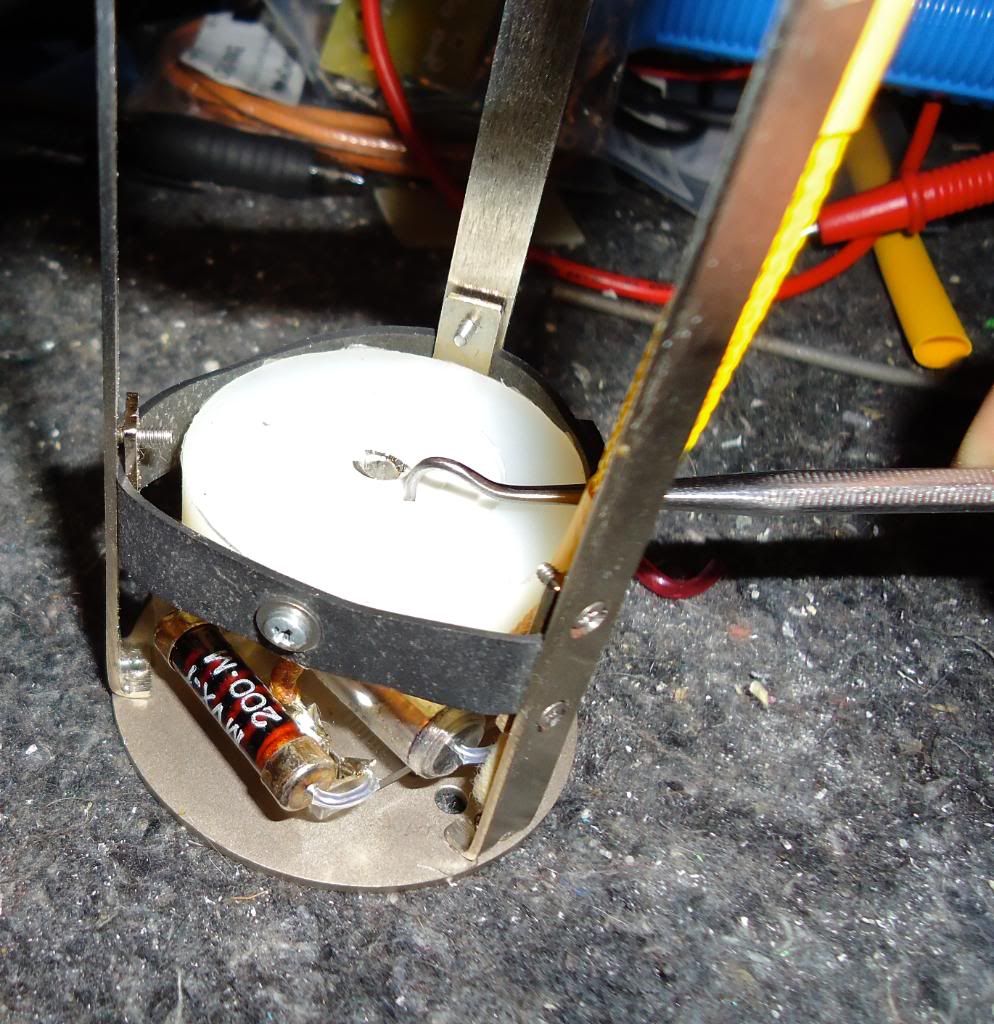
With that on ice, I decided to get to work on the crucial high-impedance portion of the mic circuitry-- the part between the capsule and the tube.
For parts here, the .01 capacitor attached to the backplate is a NOS polystyrene cap selected to be exactly .01µf. For the grid resistor and capsule polarization resistor, the original schematic listed either 60M and 100M, or 100M for both. Oliver Archut's "alt tube" EF800 schematic lists 1G for both-- he stated at least once on Klaus's forum that increasing both all the way up to 1G improves performance. I've seen other opinions to the contrary, naturally (everyone seems to have their own opinion). I decided to 'split the difference' with a couple of NOS TRW hi-meg 200M resistors. This is at least double the original spec, so it should work great. I bought a lot of 10 and wanted to select the highest-resistance ones, but I don't have a megohmmeter. What I did was to parallel them with a 2M resistor, and measure the parallel pair. A couple of them seemed to make the resistance read slightly higher, so I figured these were the highest ones. I chose those.
I also purchased some solid-core 24AWG pure silver teflon-insulated wire. I just bought a couple of feet, so it wasn't that expensive. I used/will use this for all signal-carrying wires in the mic (mainly just because I have/will have enough left over), but I bought it because I wanted to use that in this critical section. Maybe it matters, maybe it doesn't... but it was only a few bucks and I'm only building one. Why not go 'first class.'
I also have some teflon sleeving that I slipped over component leads.
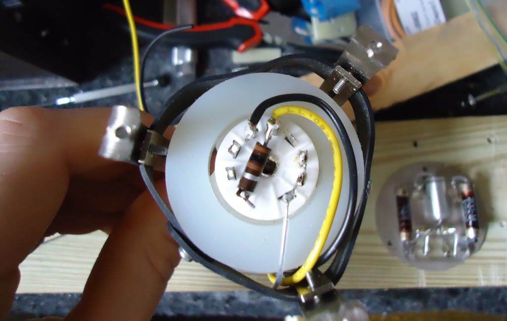
Then I added lengths of wire to the top plate for capsule polarization and master ground. I also added a strategically-positioned 29 ohm resistor which is a part of the filament/bias circuit. This is kind of like building a ship in a bottle, so everything had to be mocked up, carefully trimmed, etc. There's even a tiny piece of teflon sleeving on the short lead of that 29 ohm resistor. Besides the hi-meg resistors, all other resistors in this mic will be NOS Allen-Bradley carbon comps. I just like these resistors, and I have a good source for them, so I figured why not use my favorite resistor (others will prefer other types). I bought several of each value and selected ones that were very close in tolerance-- typically I was able to get within 1% and 2% of the stated value.
For the ground wire, I used lacquered cloth-insulated wire typical of the period-- no functional reason, just looks. For capsule polarization, I used some cool lacquered cotton-over-PVC insulated wire that was harvested long ago from a junked old Philco tuner/radio from the 1950s. Again, no reason other than looks. For the higher-current heater wires, I used modern PVC-insuated wire. Now we're ready to try and put this top plate on the mic, and make the last 2 finicky solder connections in this area.
A 100 ohm resistor for the filament/bias supply had to find a home. It fit on the tube socket itself after trimming a bit of metal from the center of the ceramic tube socket (it was on the socket, I'd guess, for a ground connection that isn't used for the EF800). Here you'll see also the 22 ga PVC-insulated stranded copper wire used for the higher-current (~275mA) filament circuit.
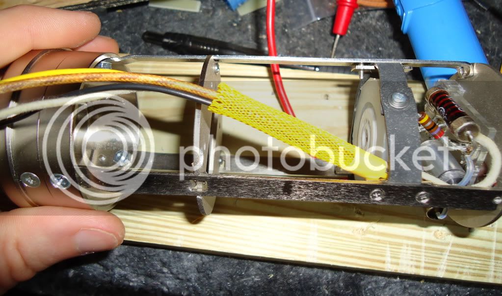
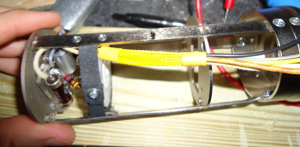
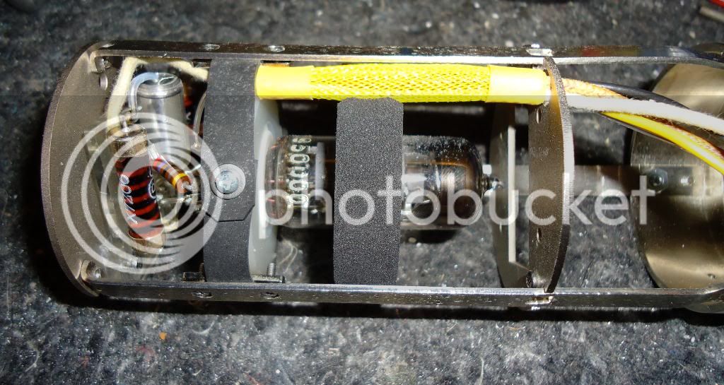
That's done! Now time to slip some TechFlex™ expandable nylon braiding over all the wires to make it look neat. I used yellow because that's consistent with what I've seen in old Neumanns. I also used some yellow heat-shrink tubing to make it all secure. First on the top...
...then on the bottom.
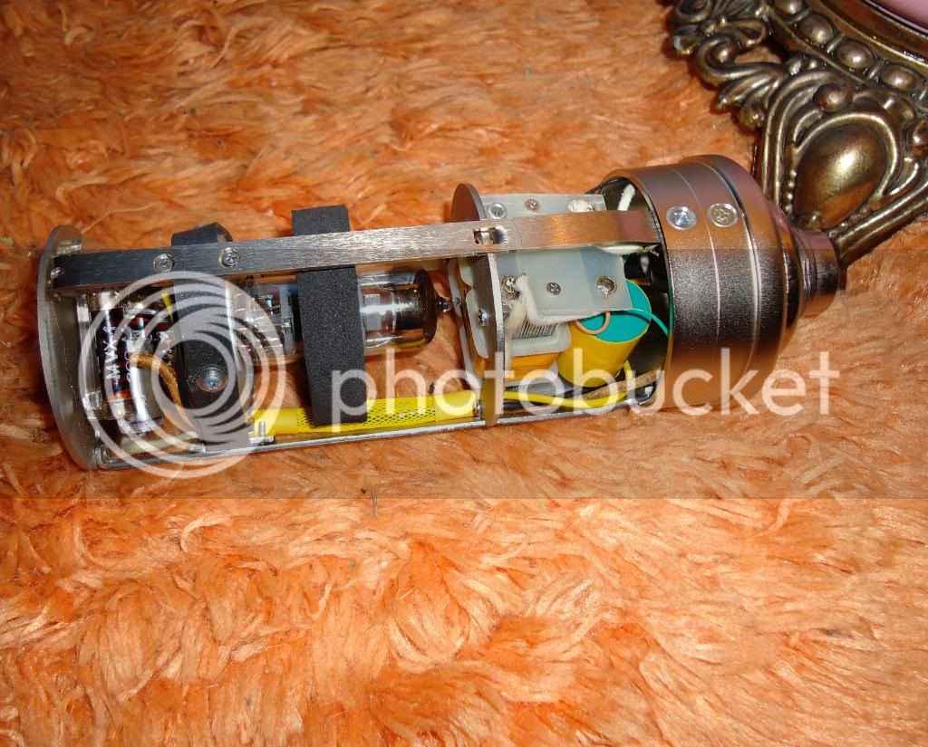
...then apply heat to shrink the heat-shrink, and stuff everything through the transformer plate. In order to get this big mess of wires through the transformer plate, I had to enlarge the hole slightly with some needle files.
I was going to put the tube in last, as that seems common sense. But since I didn't have my eyelet board making materials yet, and since building 'top down' kind of makes sense anyway (and because I could always remove it later if I had to), I decided to install the EF800 tube. Here I have two NOS Telefunken tubes from which to select the quietest/best one. I also have a donut-shaped foam tube damper purchased from eBay. I hadn't seen this style before, but it reminded me of the kind they put on the VF14 in the old Neumanns, and it was a perfect diameter, so I grabbed it.
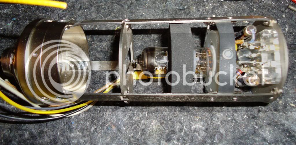
installed...
It's certainly doing something. The fit is very snug, and rapping the tube's envelope with a fingernail now gives a dull 'clunk' as opposed to a 'ping.' A test-fit reveals two issues. First is that my sleeved bundle of wires won't clear the foam donut. This is easily remedied with a few well-placed strokes of a round file.
The second issue is that the contacts in the tube socket were so tight that I couldn't insert the tube. This is the opposite problem one usually runs into with tube gear-- usually the sockets become 'sprung' over time and require re-tensioning. In this case, I had to de-tension them slightly. I used a sharp pick to ream them out just a little so that the tube could be massaged in. (sorry for the bad photo)
pretty nice fit now.
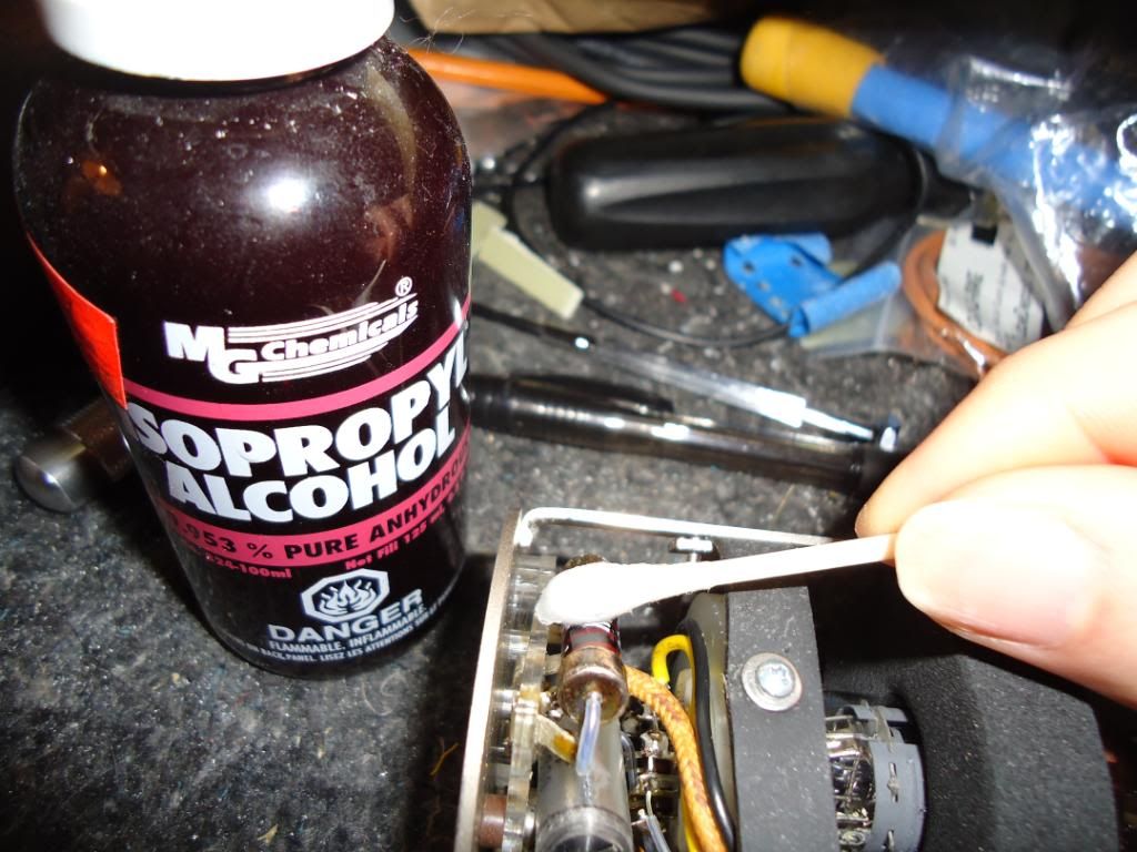
After soldering the components to the top plate and before mating to the mic body and tube socket, I cleaned all flux residue from the acrylic decking (and thoroughly cleaned the resistor and capacitor bodies themselves). After everything was all together, I took another opportunity to clean any fingerprints, etc. from this area of the mic.
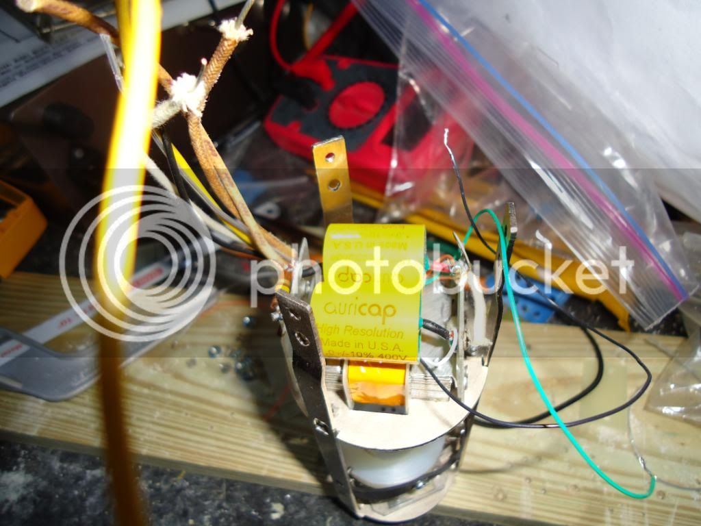
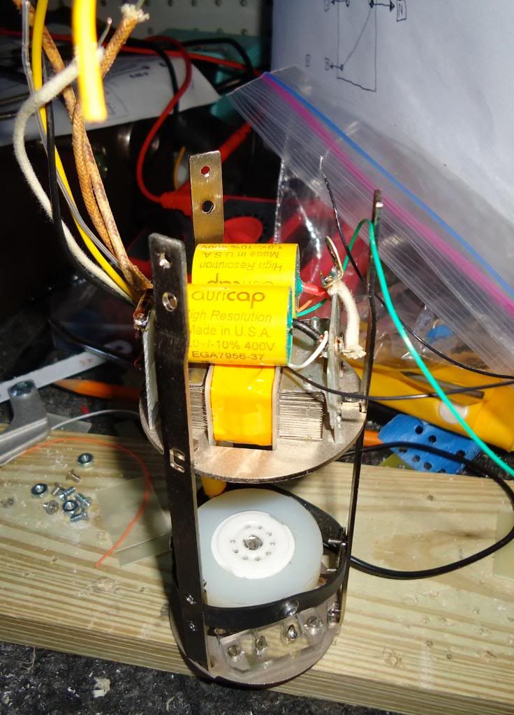
My eyelet board materials should be here soon, and I'll be able to get down to the business of putting together the lower portion of the mic. I had originally purchased vintage Sprague Vitamin Q oil-filled capacitors to use, but these proved to be far too large to fit in the microphone. I increased the coupling cap size to 1µf (from .47) as per Oliver's schematic and the advice of others (to make the response go closer to 20 Hz, instead of rolling off around 40). I ended up going with Audience Auricaps, since they would physically fit and have a decent reputation for tube circuits (without being overly large and/or expensive). I realize the coupling cap is far more critical for audio, but I admit to liking the visual symmetry of having two identical caps under the transformer. Means nothing to anyone but me, and I'm OK with that.
I have ordered a Thiersch STW-7 Blue Line PVC M7-style capsule. It will be about a month before that arrives, and by then I should be ready to complete my microphone and see if it sounds as good as I hope it will.

")