Aurycle FET Mikes

GroupDIY Audio Forum

Help Support GroupDIY Audio Forum:

This site may earn a commission from merchant affiliate links, including eBay, Amazon, and others.
If I get this or mod to a u87 how can I do the biasing procedure if I don't have a scope? Is there some place I can go to have it done or is there a cheap scope I can pickup for the couple of projects I do hear and there?

Thanks
-Scott

Would a mom and pop tv repair store have a scope to test the mic?

 
I put up a short acoustic guitar demo of this mike (please forgive my playing).  The mike is positioned about 3 feet away,aimed at the neck joint (right about the 18th fret).  There is no EQ, only a touch of reverb.  This particular guitar is solid mahogany so it starts off pretty dark in any case.

What especially comes forward is the low midrange meat of the fundamental.  The highs are there, but not hyped.  Unlike most Chinese condensers, I didn't find myself instinctively reaching for the low-pass filter.  I think with some high-pass filtering of the low's I could fit that sound in to a track.

Guitar Sample - MP3

I'd like to find someone that can try a vocal test....
 
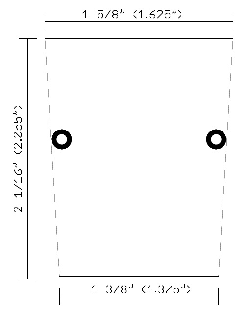
My last gift for the day.  A drawing of the board dimensions in case anyone wants to make a breadboard and/or PCB:

board_outline.jpg
 
Matador - thanks for all the documentation! This is a great thread. I am looking forward to starting my own mic project!

This looks like it's going to be a lot of fun  8)
 
Matador, it's turned out pretty well your build. Hard to tell how the finish looks with the pic but I like the colour combo you used, black and silver.

The sample doesn't sound that bad, but it be great if you A-B this with a known mic or a real u87 just to get a feel for the comparison.
 
peterc said:
My take on the 87 thing:, waiting for Aurycles to arrive.  Transformer is a Jensen 115, no audio yet....

Hi peterc, I'm just finishing up stuffing my first set of Green Pre's so welcome!

What circuit is that based from?  Standard U87 front end?
 
Hey Matador

I used the later 87 circuit, that runs off 33v:meter

http://dl.dropbox.com/u/43869772/U1621/u87%20service%20Manual%20and%20Schemo%20version%2021.PDF

I bypassed the meter and whatever the component marked D1 (TCR503) with a 47k resistor, I might have to change that to get the zener to work correctly.

Peter
 
Speaking of zeners...

Haven't seen any mention of one from you Matador.

New at this, but have come across a few warning to voltage regulate with the 2n3819, not the j305 mind...

Are you confident your voltages are safe?

This could read like  doom mongering but actually I'm hoping to learn something you know that I don't...

i.e. I don't know where to put a zener in this circuit, I know they generate airborne noise and these boards are small enough to make it difficult to get the diode far from the sensitive end, and if I can safely fit a 2n3819 without I have 10 lined up to try!!!

Any insight on the above would be most appreciated... from anyone...

Inspiring work... Thanks tonnes for the biasing run through alone...
 
Here's what a commercial modder came up with on this front:

http://www.gearslutz.com/board/gear-shoot-outs-sound-file-comparisons-audio-tests/459329-jj-audio-v67-mod-vs-u87-part-2-a.html

I have a picture of the other board (complete with zener - quite close to the fet) somewhere, just not sure which thread I got it from, when I find it I'll post it if anyone's interested.

What intrigues me (with my limited knowledge) is how this is offered with the standard transformer along with a custom jensen option (presumably with a more appropriate ratio).

Hope this informs development...
 
In order to violate the drain-gate bias maximum of 25V something terrible would have to happen to the FET itself first.  I supposed if you had a whacky phantom power spike that raised the drain bias over 25V that might do it, however one would need 70-80V on the phantom rail before that happens.  It seems a little silly to add a 75 cent Zener to protect a 55 cent FET however.

A Zener would make the biasing less dependent on the actual phantom supply voltage.  Based on the Spice simulations the circuit amplifies without issue over a fairly wide range of supply voltages, so I haven't conceived a reason to add a Zener to the circuit yet.

If you wanted to add one, you could place it in parallel with C12.  Somewhere around 35V seems right based on my measurements.
 
Thank you, that was helpful...

Found the link to the other picture if anyone is interested...
 
I got my diy460 this week and was just looking at the capsule and i notice that the gold part is flat and smooth but where the clear mylar goes under the ring with the screws on it to get sandwiched or stretch out I saw wrinkles.  They did not get that close to the gold area but the were definitely noticeable near the ring area when the light hit it right.  Looks like a drum head when its not tuned properly.  Its just in the right hand corner from like 1 O'clock to 2 O'clock

Is this something I can or should fix or should I just leave it as I will be replacing the capsule with a better one.  Will this affect the sound quality of the capsule?  I know its a cheap one but still.


saxmonster said:
I got my diy460 this week and was just looking at the capsule and i notice that the gold part is flat and smooth but where the clear mylar goes under the ring with the screws on it to get sandwiched or stretch out I saw wrinkles.  They did not get that close to the gold area but the were definitely noticeable near the ring area when the light hit it right.  Looks like a drum head when its not tuned properly.  Its just in the right hand corner from like 1 O'clock to 2 O'clock

Is this something I can or should fix or should I just leave it as I will be replacing the capsule with a better one.  Will this affect the sound quality of the capsule?  I know its a cheap one but still.

That is nearly impossible to "fix" without a whole capsule re-haul. Sometimes the crinkles don't effect sound, other-times they do. My guess is it probably looks worse than it sounds.
 
saxmonster said:
I got my diy460 this week and was just looking at the capsule and i notice that the gold part is flat and smooth but where the clear mylar goes under the ring with the screws on it to get sandwiched or stretch out I saw wrinkles.  They did not get that close to the gold area but the were definitely noticeable near the ring area when the light hit it right.  Looks like a drum head when its not tuned properly.  Its just in the right hand corner from like 1 O'clock to 2 O'clock

Is this something I can or should fix or should I just leave it as I will be replacing the capsule with a better one.  Will this affect the sound quality of the capsule?  I know its a cheap one but still.

I received a capsule in similar state from Aurycle.  It must have slipped through Quality Control somewhere.  Aurycle replaced it for me.

David
 
Thanks again Matador, this thread has been thoroughly inspiring. A fet change, some cap swapping and all the fun of biasing by ear and my 24ukp chinese xfrmr mic outclasses a lot more expensive stuff.  Nice strong signal too, on a par with my rode stuff and only a little noisier. Completely trashes my stock v67g for clarity and makes an nt1a sound brittle across the spectrum.  Wondering about going wild over esoteric capacitors but I get a feeling the mic already deserves a better capsule...
 
Been toying with the action of C3 against C5 and the capsule capacitance.

C3 sets the amount of AC negative feedback that is coupled through the capsule bias, and adjusting the value changes where HF de-emphasis happens in the frequency domain.

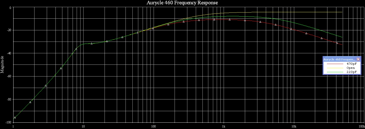
Here is a SPICE of three cases:

a460_freq.jpg


So you can see that removing C3 (yellow line) increases gain (and output impedance) to maximum and it's basically flat out until the transformer L takes over (not shown in the perfect transformer model).  The stock 220pF value (green line) is 3db down at about 7kHz (and 3db down overall in the passband).  Going up to 470pF (red line) drops gain overall by 3dB again and reduces the 3dB down point to about 4kHz.

I'm toying with the idea of getting rid of the -10dB pad switch (which pretty much all of my preamps have on their inputs) and converting it to a de-emphasis adjustment switch.  So the two options would be "open" meaning the circuit is flat, and "closed" would give the de-emphasis at 7kHz.  This might open up a few options where removing the de-emphasis is enough to put a bit more "air" into the sound on dark sources.

I can see why this circuit is popular with the Chinese re-branders, as you can put in a shrill K67 clone capsule then tame the shrillness down with the feedback loop.
 
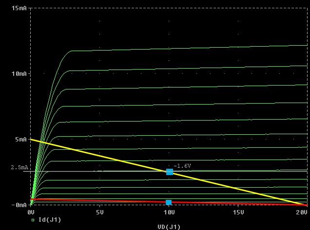
I'm also looking at the biasing of the FET in the U87 design.  The drain resistor is 47K, which means that IDS cannot by definition be higher than about 0.5mA (assuming a VDD of 21.5V per the schematic).

If you plot this load line on the 2N3819 (the red line below) you can see that the input voltage swing is pretty severely limited:

2n3819_bias.jpg


The simulation matches:  signals beyond about 0.2V peak get clipped when the gate-source bias goes positive.

I'm wondering about choosing a higher Q point for the FET, more up into the 2.5mA idle range (yellow load line on the plot).  This would move the maximum input amplitude up above 0.5V peak before clipping, and even more important is the output impedance of the stage falls by almost factor of 10 (from 47K down to about 6K).  I would guess that THD is much less as the slope of the VGS/IDS curve at this Q point is closest to a straight line.

I wonder why such a low idling point was originally chosen:  was it a phantom power / current consideration?  Pulling 2.5mA - 5mA doesn't stress out any phantom power supply (which is specified for 14mA into a dead short), I wonder what Neumann was thinking?  Perhaps the capsules were capable of putting out much signal so the extra current doesn't buy better operation?
 
In the original Neumann U87 circuit, each mA of current drawn - drops the available microphone voltage by ~ 4.5 volts.
a draw of 2.5 mA would drop the available voltage by 48 - 11.25 volts. The resulting 36.75 volts is then  the capsule polarizing voltage.
A 5 mA draw would result in only 25.5 volts for capsule polarizing voltage.

Cheers.

ZAP
 

Latest posts

Back
Top