Aurycle FET Mikes

GroupDIY Audio Forum

Help Support GroupDIY Audio Forum:

This site may earn a commission from merchant affiliate links, including eBay, Amazon, and others.
Hey Matador-really enjoying your attention to detail, and this discussion.
It has been mentioned before on this forum that C3 acts as a LPF, but this is the best explanation I've seen of why that is so.
 
zapnspark said:
In the original Neumann U87 circuit, each mA of current drawn - drops the available microphone voltage by ~ 4.5 volts.
a draw of 2.5 mA would drop the available voltage by 48 - 11.25 volts. The resulting 36.75 volts is then  the capsule polarizing voltage.
A 5 mA draw would result in only 25.5 volts for capsule polarizing voltage.

Cheers.

ZAP

Hi Zap....of course!  Neglecting the 2.21K resistors in my sim was obviously short-sighted. ;)

I feel that a DC-DC converter board is now on my plate. ;)
 
Matador said:
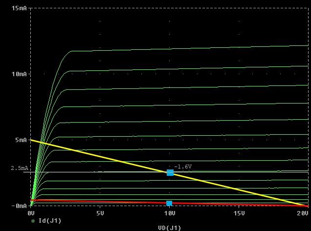
I'm also looking at the biasing of the FET in the U87 design.  The drain resistor is 47K, which means that IDS cannot by definition be higher than about 0.5mA (assuming a VDD of 21.5V per the schematic).

If you plot this load line on the 2N3819 (the red line below) you can see that the input voltage swing is pretty severely limited:

2n3819_bias.jpg


The simulation matches:  signals beyond about 0.2V peak get clipped when the gate-source bias goes positive.

EDIT: this is wrong.  It gets clipped when the transistor enters the linear region and drain current falls away.

I'm wondering about choosing a higher Q point for the FET, more up into the 2.5mA idle range (yellow load line on the plot).  This would move the maximum input amplitude up above 0.5V peak before clipping, and even more important is the output impedance of the stage falls by almost factor of 10 (from 47K down to about 6K).  I would guess that THD is much less as the slope of the VGS/IDS curve at this Q point is closest to a straight line.

I wonder why such a low idling point was originally chosen:  was it a phantom power / current consideration?  Pulling 2.5mA - 5mA doesn't stress out any phantom power supply (which is specified for 14mA into a dead short), I wonder what Neumann was thinking?  Perhaps the capsules were capable of putting out much signal so the extra current doesn't buy better operation?
 
Started to build the dit kit tonight organizing everything first but man its hard to read the resistors. Anyone know of a good chart online.  I can't tell if the stripes are brown or orange, purple or blue.  What is the best way to read these? Errrrr.  I need rest.  Would doing it in the day light help? instead of a flash light and table light.

 
Got a meter? I usually double-check resistors with my meter before soldering them in.
Saves a lot of looking for errors later.
 
saxmonster said:
Started to build the dit kit tonight organizing everything first but man its hard to read the resistors. Anyone know of a good chart online.  I can't tell if the stripes are brown or orange, purple or blue.  What is the best way to read these? Errrrr.  I need rest.  Would doing it in the day light help? instead of a flash light and table light.
I sometimes have to use a good flashlight and reading glasses, or a loupe/magnifying glass and find that the colours stand out better.

David
 
I would just measure them with a DMM...unless you get really good at reading them. But then you still want to measure to double check, like was mentioned before
 
I Doubled check everything in the sun light today, much easier, at the kitchen table today and all looks ok I will check them with the tester tomorrow and then install them. 
 
Got my build done tonight.  Pretty easy once I knew what resistors were what.  Sounds pretty good with just the mic check 123.  Will do some recording this week and then once all the parts for the u87 mod get here I will build those boards and install.
 

Attachments

  • photo 1.JPG
    photo 1.JPG
    621.7 KB · Views: 128
Here's another idea I have bandied about:

aurycle_testboard.jpg


It's essentially a "Veroboard" specifically to be mounted inside of a Aurycle (or other host of U87 clone) mike bodies.

You can see in the middle, there is a top-layer pour for a VDD net.  There are 7 connections along the bottom for the XLR/output transformer and 7 connections along the top for capsule/switch connections.  There is a strip of GND nets along side of the VDD pour (you can see the thermal reliefs), and the bottom pour (in blue) is all GND.

I think something like this would be cool for those wishing to experiment with different mike circuits but have something that would be solid enough to remain in the mike long-term.  The grid is 0.1" so a lot of standard DIP IC's and headers would fit, and there's enough interconnected grid points for 60 net's worth of circuits (per board).  Components could be mounted on top from net to net, and jumpers could be wired vertically on the underside of the board without too much mess.

Perhaps poctop may be interested in doing a board run of this if I released the Gerber files to him? (hint, hint)  ;D

I'm working on an overlay of the basic KM84 circuit on top of this to see if it makes sense  (and get an idea of how many jumpers would be needed).
 
That's a pretty awesome idea.

I might add some holes for hi-z section teflon standoff's. The kind with posts on both sides. I don't know if seven would fit across the top but it would be nice to have at least three of these standoff's and maybe more for experiments.

Cheers,
jonathan
 
just got mine in today. didnt take too long, sounds pretty good. i plan or using it for the u87 in the white market though.
 
0dbfs said:
I might add some holes for hi-z section teflon standoff's. The kind with posts on both sides. I don't know if seven would fit across the top but it would be nice to have at least three of these standoff's and maybe more for experiments.

Do you know of a source for these insulators?
 
Actually I found them:  Keystone electronics PTFE insulated pins part #11216.

How about something like this (assuming JFETs with center gate connections)?

aurycle_vb2.jpg


Input JFET gate resistor could be soldered between the right-most insulated pin and a ground via.  The input cap could be soldered across/over to the middle insulated terminal, which would be the capsule connection (and possibly another high value resistor to ground).

Actually I might add a 4th post, as this would fully accommodate a dual-disphram, dual-backplate capsule....
 
Another version.  1 more high Z post on the top, and I bridged all of the two-hole connections up to 4 (thinking that at minimum, a net must hold at least 1 wire, so having only two holes per net doesn't make much sense).  This reduces the total number of nets down to 44 (from 60) but all 44 should be usable.

aurycle_vb3.jpg
 
Did anyone check this thread for an adjustment to the circuit.
http://www.groupdiy.com/index.php?topic=47569.0
I have changed one of my stock MXLV67s to this.
Compare the schematics
 
I got to test this Diy 460 mic un modded last night and all I can say is it is bright.  I compared it to my akg414 buls and an mxl144r and it was the brightest one out of the three.  All the qualities were there it was just very bright.  Not very musical bright.  Kind of annoying bright.  I going to mod it in a u87 and will post the results from that later.

Peace.

-Scott
 
Had a play with this today and got a good way into neumannising a prebuilt variant of this china xfrmr type. Linux style oscilloscoped a netbook, swapped the fet, fitted a trimmer, pulled the emitter follower and the bootstrapping. Clear improvement with the biased 2n3819, got a little noisy without the follower (all caps remained stock - guessing c8 needs a body stretching cap in this config) and then died to a heartbeat style pulse after I attempted to measure the drain voltage.  Guessing I killed the fet.  Can someone wiser confirm so I can sleep soundly and stop itching to go back out to the garage...  Will get another and attempt Gus's mods and some EQ messing before amalgamating what I learn...  Thanks again Matador.
 
Came back to it after a good nights sleep and a trimmer tweak after a false dmm reading and all is now well. Added a bypass wima to the stock c8 as I didn't have anything in the league I want to replace it with. Up against the stock cheap china transformer condenser it sounds sharp and quiet. Same too against a MXL V67g.  Up against a Rode NT1a it sounds noisier, less rhythmically precise but more tonally clear (psychological? the percussive nt1a masking subtler pitch change I think) - using a guitar as source which didn't expose the nt1a's weaknesses much.  I'm impressed.  I'd rather have it than a stock mxl v67g and I have no doubt from previous experiments it will be favoured by my vocalists over  the Rodes. My naivety re electronics meant I expected the circuit to mourn the emitter follower.  But no, it's got a new lease of life with no obvious downsides. Any none obvious ones I might be missing? From here what improvements could I expect from a better transformer?
 
Back
Top