You are using an out of date browser. It may not display this or other websites correctly.
You should upgrade or use an alternative browser.
You should upgrade or use an alternative browser.
[BUILD] 1176 Rev A - Back to the beginning...
- Thread starter mnats
- Start date


Help Support GroupDIY Audio Forum:
This site may earn a commission from merchant affiliate
links, including eBay, Amazon, and others.
Spencerleehorton
Well-known member
Hi,
I have question for you all.
The standing DC current through Q6 is determined by the voltage on its emitter divided by R32 (39ohms), assuming that the transformer winding connected to Q6 emitter has zero resistance. If you work this out you get 56mA.
The voltage across Q6 is about 25V. This results in a dissipation in Q6 of 1.4W which it cannot deal with and gets very hot, resulting in thermal ranaway and burnt out R32.
If the resistance of the transformer winding connected to Q6 emitter is something of the order of 150ohms the working conditions of Q6 become much more sensible, with a standing current of about 12mA (2.2V/189ohms) and a dissipation of 300mW (25*.012).
So my question is, can anyone tell me the total winding spec. for the output transformer, particularly the details of the winding connected to Q6 emitter, particularly its DC resistance?
blackartmixing
Active member
- Joined
- Dec 18, 2013
- Messages
- 34
Hairball Audio said:blackartmixing said:could you give me a quick explanation of how to check the voltages please? where should i connect the red and black leads from my DWW?? and what should i expect to see? thanks
http://mnats.net/files/1176REVA_125_VOLTAGES.pdf
Put your black on common again, test for DC, google/datasheets will help you identify leads.
do i have to have the 1khz signal running into the input to check these?
blackartmixing
Active member
- Joined
- Dec 18, 2013
- Messages
- 34
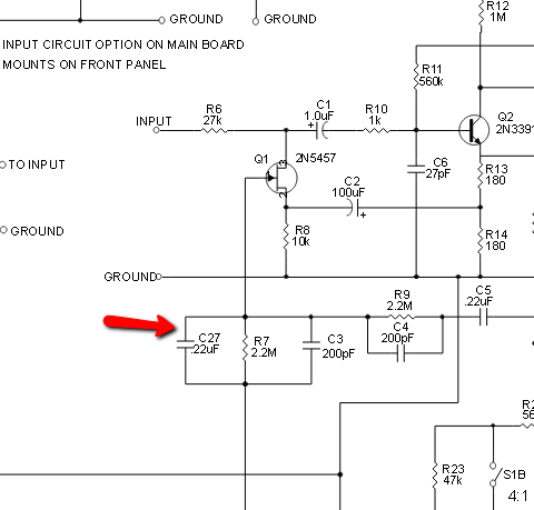
so i figured out how to take the reading ") small victories and learning a lot. the only place where is seems to be a bit suspect is Q4. i get 1.76 on the pin nearest the front panel, 4.18 on the middle and 12.73 on the far pin. according to the schematic it should be 6.6V and 13.72V so my values seems pretty low. strangely i had a J309 transistor spare so i swapped it out with that but still the same issue. I checked all the transistors and they are the correct type. any ideas what i should check next?
small victories and learning a lot. the only place where is seems to be a bit suspect is Q4. i get 1.76 on the pin nearest the front panel, 4.18 on the middle and 12.73 on the far pin. according to the schematic it should be 6.6V and 13.72V so my values seems pretty low. strangely i had a J309 transistor spare so i swapped it out with that but still the same issue. I checked all the transistors and they are the correct type. any ideas what i should check next?
small victories and learning a lot. the only place where is seems to be a bit suspect is Q4. i get 1.76 on the pin nearest the front panel, 4.18 on the middle and 12.73 on the far pin. according to the schematic it should be 6.6V and 13.72V so my values seems pretty low. strangely i had a J309 transistor spare so i swapped it out with that but still the same issue. I checked all the transistors and they are the correct type. any ideas what i should check next?Echo North
Well-known member
blackartmixing said:so i figured out how to take the reading
Check all the transistor values. Re-flow any odd joints.
Mike
blackartmixing
Active member
- Joined
- Dec 18, 2013
- Messages
- 34
Hairball Audio said:blackartmixing said:so i figured out how to take the reading
Check all the transistor values. Re-flow any odd joints.
Mike
as i said above i have checked all the transistors and they seem to measure correctly according to the schematic except possibly at Q4. in your opinion do the values above look incorrect? or should i look somewhere else?
Echo North
Well-known member
blackartmixing said:Hairball Audio said:blackartmixing said:so i figured out how to take the reading
Check all the transistor values. Re-flow any odd joints.
Mike
as i said above i have checked all the transistors and they seem to measure correctly according to the schematic except possibly at Q4. in your opinion do the values above look incorrect? or should i look somewhere else?
They are a little weird. Have you looked at the resistors in the area? They are part of what sets those voltages.
blackartmixing
Active member
- Joined
- Dec 18, 2013
- Messages
- 34
i tested R24 and its measuring 17 M resistance instead of 15 M. could this be an issue?
blackartmixing : if you used a 5% tolerance resistor there, its still out of the tolerance range
Low Tolerance Value: 14250000 Ohm
High Tolerance Value: 15750000 Ohm
did you measure it out of the circuit?
***
could you please tell me whats the best S/N we can have with rev.A rack builds? i know its not "LN", but im very curious if i should fight for less noise - or this amount of noise is a "feature".
my observation is the input gain doesnt really affect the overall noise, its coming from the out amp i guess?
Q6 gets very hot (tho i have a small heatsink on it). i guess thats normal, but.. this hot?
i dont see much buzz/hum on the output, its mostly white (?) noise.
blackartmixing
Active member
- Joined
- Dec 18, 2013
- Messages
- 34
thanks Tata. and yes i took it out of circuit. so what should i do? i guess its up to me to procure a new 15 M resistor?
blackartmixing : well, i would do that. not sure if it will fix your issue tho.
***
im redoing the internal wiring atm, using shielded cables, and i just had an intresing observation : if i turn up the out gain to maxx, i get a "pop" in the signal, VU moves, and the noise jumps up to a very high level. there is also sort of a "radio tuning" sound on the output. if i touch the pins of the out XLR and push em gently this noise and the "squeek" disappears, unit works as it should.
can you pls teach me what is happening in there? sure i can solder the wires, making the best possible contact, etc - but id like to learn about this "effect". stray capacitance? other?
---- EDIT : -----
"Make sure these red and blue VU meter wires are long enough to route them well clear of the input circuit on the main PCB or you will have problems with feedback at high gain." - problem solved.
-----------------
another observation is : using shileded cables for internal wiring makes not as much difference as i thought.
maybe im doing something totally wrong - or i just had luck with the unshielded wiring?
thanks
Ragan
Member
- Joined
- Feb 29, 2016
- Messages
- 5
Hello. I hope this is the correct place for this. If there is a sub-thread for extra stupid or extra-newb questions, I will gladly head there immediately.
I just picked up the Hairball Rev A 500 kit, which is demonstrably over my head (I knew that before I bought it). I've never built any real electronics before. I've done of lot of soldering of cables, guitar pickups, switches, pots, jacks and that kind of thing. I've also modded a few mics. Nothing difficult.
Anyway, I'm determined to go slow and methodically and get this thing built. I don't mind if it takes a long time.
So here are my stupid questions:
I'm attempting to go over the bill of materials and make sure I have everything, as suggested, and I don't really understand what I'm doing.
There's this page on the Hairball site:
http://library.hairballaudio.com/maps/reva500/
And there's this mnats page:
http://mnats.net/files/FET-A500.pdf
But I'm not really sure how to sort of 'check things off' as I look through the bags. The Hairball page lets you highlight components but I don't really get what I'm doing. I pull, say a resistor, out of the bag and look at it, how do I find that particular part on the diagram?
Edit: maybe I just measure it, get the value, find a resistor with that value on the diagram and highlight it, then move on? Just typing out these questions is helping me get a grasp on this I think. The part numbers seem to be R for resistor, C for capacitor, Q for...transistor?
Next stupid question:
I assume these bags (see attached pic) indicate the range of resistors inside and the bottom bag is just indicating 'greater than' 100 kiloohms, yes?
As I put the meter on them, should I label their values? Seems like I should. Or I could just remeasure before soldering each one.
Also, when I put my DMM leads on some of these resistors, I'm not getting a reading, it just stays at "1". Others, I get a reading but it's sometimes jumping around. Is my meter the culprit? It's pretty cheap, this one to be exact:
http://www.ruralking.com/digital-economy-tester-18-range-gdt311-gdt11-by-gb-electrical.html?fee=2&fep=68045&utm_source=google&utm_medium=cpc&gclid=CjwKEAiA9om3BRDpzvihsdGnhTwSJAAkSewLvapHP_5Meafk_EFxix1fksjv2Wb9RzOqmRAO8jybaRoCaIjw_wcB
I'll gladly get a new meter if you guys think that's why I'm not getting good readings here. I've only ever used it on guitar electronics.
Edit: ok, so the color pattern indicates what their value should be (I knew that, just wasn't applying it to this situation), I should just check to make sure they all measure what they should, right? Don't need to label every piece, just make sure it's what it's supposed to be....I think....
Thanks for any help. Please go easy on me. I certainly don't know what I'm doing but I'm a quick study. I'm a builder by trade so I'm used to working with materials in general and I've done a lot of residential electrical. I know that doesn't really cross over here but I'm used staying the course on long projects with ups and downs (the remodel I just finished took me a year...)
Attachments

Ragan
Member
- Joined
- Feb 29, 2016
- Messages
- 5

Ragan,
i think you do the best if if re-measure every singe resistor before soldering them in. when your DMM shows "1" that usually means the value is higher than the measurement range, so you gotta change the range. for eg you cant measure a 22k at in the 20k range, that shows "1". you need to set it to 200k range.
the blue Bourns things are trimmers. (multiturn, miniature potentiometers)
Ragan
Member
- Joined
- Feb 29, 2016
- Messages
- 5
tata said:Ragan,
i think you do the best if if re-measure every singe resistor before soldering them in. when your DMM shows "1" that usually means the value is higher than the measurement range, so you gotta change the range. for eg you cant measure a 22k at in the 20k range, that shows "1". you need to set it to 200k range.
the blue Bourns things are trimmers. (multiturn, miniature potentiometers)
Thank you. Appreciate the response.
The DMM range setting thing occurred to me too but I was getting some "1" readings even at the highest range which, according to the bag, should have been higher than the resistor by a factor of 10 or something.
My good buddy is an electrician and has a Fluke bench meter he never uses so I'm going to borrow it and see what it's saying.
Edit: also, I just noticed those trim pots are right there with pics in the build guide...FACEPALM TO ME
whats the best way to get +24VDC for a pair of DPDT relays in rev.A, please?
should i get it from the 7824, from the +30V rail with another stabilizer added, or a separate PSU from the AC trafo?
is +29.1V enough on the +30V rail (loaded, w/the VU lamp too)? i use a 2x24V 50VA trafo.
thanks
should i get it from the 7824, from the +30V rail with another stabilizer added, or a separate PSU from the AC trafo?
is +29.1V enough on the +30V rail (loaded, w/the VU lamp too)? i use a 2x24V 50VA trafo.
thanks
Echo North
Well-known member
tata said:whats the best way to get +24VDC for a pair of DPDT relays in rev.A, please?
should i get it from the 7824, from the +30V rail with another stabilizer added, or a separate PSU from the AC trafo?
is +29.1V enough on the +30V rail (loaded, w/the VU lamp too)? i use a 2x24V 50VA trafo.
thanks
I'd use the 30V rail and a dropping resistor. Just figure out the current draw of the relay coil and use a little ohms law to calculate the 6V drop. Your transformer should easily be able to handle the load.
Echo North
Well-known member
tata said:blackartmixing : if you used a 5% tolerance resistor there, its still out of the tolerance range
Low Tolerance Value: 14250000 Ohm
High Tolerance Value: 15750000 Ohm
did you measure it out of the circuit?
***
could you please tell me whats the best S/N we can have with rev.A rack builds? i know its not "LN", but im very curious if i should fight for less noise - or this amount of noise is a "feature".
my observation is the input gain doesnt really affect the overall noise, its coming from the out amp i guess?
Q6 gets very hot (tho i have a small heatsink on it). i guess thats normal, but.. this hot?
i dont see much buzz/hum on the output, its mostly white (?) noise.
Measuring resistor that high is not really possible with a common meter. Using the DMM is more of a double check after you read the color code. Just to make sure you're in the ballpark.
Similar threads
- Replies
- 10
- Views
- 1K