Rob Flinn
Well-known member
Anyone got a source for the 2n3391 in the UK, or know of a suitable substitute that is obtainable ??


") The latest in a long line of cretinous updates from the biggest numpty on the forum is that I have decided to start a new board & so ordered parts from Mouser & Mnats ??? ??? I then ripped a trimmer out, R44 which didn't click at either end of it's turning cycle, replaced a dodgy alpha attack pot & bingo I seem to have a almost working build
The latest in a long line of cretinous updates from the biggest numpty on the forum is that I have decided to start a new board & so ordered parts from Mouser & Mnats ??? ??? I then ripped a trimmer out, R44 which didn't click at either end of it's turning cycle, replaced a dodgy alpha attack pot & bingo I seem to have a almost working build simonlef said:4:1 is 5.5:1, 8:1 is 9:1, 12:1 is 14:1 and 20:1 is 24:1.


Echo North said:simonlef said:4:1 is 5.5:1, 8:1 is 9:1, 12:1 is 14:1 and 20:1 is 24:1.
This is normal. It's a discrete circuit so nothing will be spot on. These ratio's looks good to me.
dmp said:Either describing or posting a graph of how you measured the ratio would be interesting.
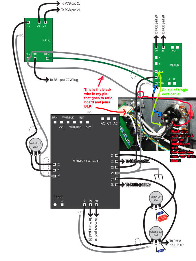
canidoit said:I wired that section like this, which is correct from what I recall.bdubya said:The wires labelled "N.C." are not connected at one end, but tied to ground at the other end, or to another wire that itself travels to ground, and should be the shield of another wire. For instance, the wire travelling between pad 22 on the main board and pad 22 on the meter board should be a shielded one, with its shield attached at the main pcb to the adjacent ground pad, but cut short as close to the meter pcb as possible, with shrink wrap or some other precaution in place to avoid shorting things. Looks like his shields are all grey in his diagram. Hope that helps.
Enter your email address to join:

