Channel strip balanced output stage - oscillation pbm

GroupDIY Audio Forum

Help Support GroupDIY Audio Forum:

This site may earn a commission from merchant affiliate links, including eBay, Amazon, and others.

saint gillis

Well-known member
Joined
Nov 4, 2012
Messages
890
Location
Brussels - Belgium
Hi mates, I ve put in a rack two Studer 900 channel strips, here's the schematic
http://img839.imageshack.us/img839/6312/26lm.jpg
I took the Pre-Fader output ( just next to "Low Equalizer" on the schematic" )
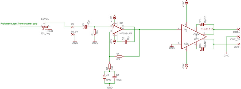
  But it is a 0db output, so I need to convert it to a balanced +6db output, first of all I ve tried to duplicate the circuit used in the Studer 900 's faders :
65yn.jpg

Unfortunately I had an offset problem, positive output with much more gain than negative output, rather than trying to adjust the resistors values I tried an other design, here it is:
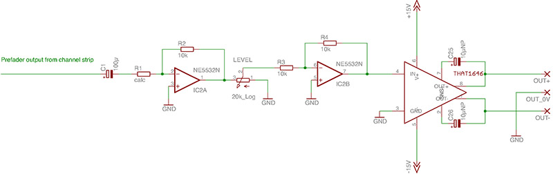
The Pre-Fader output goes throught a 22KLog "Level" pot then to this circuit :
http://img541.imageshack.us/img541/5875/vt4w.jpg
There is an amplifying stage calculated to get the same input and output line levels when the 22kLog pot added is at its mid-point, then a mixed feedback driving circuit for a LL2811 output transformer wired in 1:2.

  My problem is that I sometimes got some kind of auto-oscillation at the output, when I switch the device off and on everything comes back to a normal behaviour and the sound is perfect, any advice?
 
If you copied the schematic from the image you posted make sure you are driving the two output opamps from a low impedance. The circuit shown uses a dedicated buffer opamp. Console designers don't throw extra opamps around for fun...

JR
 
Taking NFB from the far end of the 22 ohm isolator is dubious.

Why is there a freight-train of low gain inverters?
 

Attachments

  • saintgillis-mod.gif
    saintgillis-mod.gif
    10.9 KB · Views: 86
saint gillis said:
Unfortunately I had an offset problem, positive output with much more gain than negative output, rather than trying to adjust the resistors values ...
These cross-coupled output circuits attempt to be like floating transformer outputs.

If you measure the outputs individually, you'll find one will be greater than the other UNLESS you short the other side out.  Naive makers have fancy twiddle procedures to get both sides 'balanced'.

But the important thing is whether both sides overload at the same time.  Just put your 10k, 600R bla bla load across the output and scope both legs simultaneously.  If both legs overload at the same time and equally on +ve & -ve, everything is OK

I've not seen your version of the cross-coupled output so dunno how good it is compared to tried & tested versions.  There are loads, some better than others.  The THAT devices do it all for you and very nicely too ... without tweaking & extra bits.
 
Thank you Ricardo, I should have mesured it loaded, of course how naive I am..

Now I was wondering why in the driving circuit suggested in the Lundahl2811 datasheet R1 was inside the feedbackloop :
http://www.lundahl.se/pdf/2811.pdf

I found some interesting thoughts here :
http://tangentsoft.net/audio/hs-opamp.html
"Add a small resistor to the op-amp's output, either inside or outside the feedback loop. (10-100 Ω) This isolates the op-amp from any load capacitance. I prefer putting it inside the feedback loop, because op-amp feedback will counteract some of the bad effects of having the resistor, yet the resistor will remain effective. Others recommend putting it outside the loop, so that it can protect both the OUT and the -IN op-amp pins. This raises the amplifier's output impedance, though, which is not without consequences."
 
saint gillis said:
Thank you Ricardo, I should have mesured it loaded, of course how naive I am..

Now I was wondering why in the driving circuit suggested in the Lundahl2811 datasheet R1 was inside the feedbackloop :
http://www.lundahl.se/pdf/2811.pdf
Looks like a transformer thing,,, The way the NF is configured the top of the winding is getting the actual input voltage. The bottom of the winding is getting inverted version of that input + a voltage = to the current through R1. I think this effectively drives the transformer from a negative impedance, perhaps to partially compensate for winding impedance of transformer secondary? (Guessing because I'm, not a big transformer advicate.
I found some interesting thoughts here :
http://tangentsoft.net/audio/hs-opamp.html
"Add a small resistor to the op-amp's output, either inside or outside the feedback loop. (10-100 Ω) This isolates the op-amp from any load capacitance. I prefer putting it inside the feedback loop, because op-amp feedback will counteract some of the bad effects of having the resistor, yet the resistor will remain effective. Others recommend putting it outside the loop, so that it can protect both the OUT and the -IN op-amp pins. This raises the amplifier's output impedance, though, which is not without consequences."
When you put the resistor inside the NF loop,  any capacitance on the output alters the NF closed loop gain. This can reduce HF headroom, and perhaps cause other errors. It is not uncommon to add diode clamps to rails at opamp output to protect from the customers and outside world.

JR
 
I ve wired the primaries in parallel, that why I choosed a 22r resistor, maybe it is there that the cause of my problems is hidden, remember it is the negative output that sometimes oscillate...
 
JohnRoberts said:
Looks like a transformer thing,,, The way the NF is configured the top of the winding is getting the actual input voltage. The bottom of the winding is getting inverted version of that input + a voltage = to the current through R1. I think this effectively drives the transformer from a negative impedance, perhaps to partially compensate for winding impedance of transformer secondary? (Guessing because I'm, not a big transformer advicate.
There's another Lundahl application note 'Mixed feedback drive circuits for audio output transformers' that mentions German patent DE 29 01 567 with application day 13.1.79 for this.

At Calrec, Ken Farrar came up with something which we used with great success.  Search for Calrec 1496.  (We went away from the balanced i/p on that dwg)  It was all about the same time as the German patent but Ken always claimed it was his own invention. The Calrec version differs substantially from the German as well as the Lundahl.

You can't cancel ALL the transformer resistance (You do it to 'eliminate' 3rd harmonic due to the core).

Like JR, I'm not a fan of transformers for output these days (was in Jurassic times) but this Calrec circuit has some advantages that would be impossible without transformers.  However the applications are all wholly evil so I probably won't ever do one again  :eek:

But Saint, if you are prepared to pay for a Lundahl 2811, why not use a THAT 1646 which does what the Studer tries to do but properly.
 
saint gillis said:
Ricardo you mean a that 1646 to drive the LL2811?
No.  THAT1646 is a solid state equivalent of a transformer.  It does what the Studer circuit tries to do but properly.

It's performance is better than any transformer circuit except for my exotic application that no one else uses.

Adding a transformer to THAT1646 will only degrade its performance.
 
Ricardo you are pissing up a rope trying to talk people out of transformers. The kool-aid in them is strong.

I would be more forceful with a junior engineer working for me than some hobby DIY-ers who are easily separated from their money and time.

Transformers are pretty much harmless if you have too much money burning a hole in your pocket. Better than them spending it on crack or pain killers. (or tubes).  8)

JR

PS: No offense to transformer advocates, Ricardo knows more than I do about them but we seem to be of a similar mind set regarding their place in the food chain. 
 
JohnRoberts said:
Ricardo you are pissing up a rope trying to talk people out of transformers. The kool-aid in them is strong.

I would be more forceful with a junior engineer working for me than some hobby DIY-ers who are easily separated from their money and time.

Transformers are pretty much harmless if you have too much money burning a hole in your pocket. Better than them spending it on crack or pain killers. (or tubes).  8)

PS: No offense to transformer advocates, Ricardo knows more than I do about them but we seem to be of a similar mind set regarding their place in the food chain.
ROTFL  ;D

JR, you forgot about the extra mass of transformers.  Never mind the quality  ...  feel the weight!  :)
 
So if I want to add a balanced output stage with a 8.5 gain, I should just put a non-inverting aop + a THAT 1646 ?

  I just wish to get the most versatile stuff in my studio, being able to plug balanced into unbalanced and vice-versa; and I got those transformers for a correct price (40$ the pair) I already made some api preamps clones with them and I m really happy with them, so I don't think it's a waste of money, of course if I was planing to build some stuff in industrial quantities I would not use audio transformers, it is not the case...  but I'm open minded, the only thing I want is the most convenient in my studio, transformers or not I don't care!
 
 
saint gillis said:
So if I want to add a balanced output stage with a 8.5 gain, I should just put a non-inverting aop + a THAT 1646 ?

  I just wish to get the most versatile stuff in my studio, being able to plug balanced into unbalanced and vice-versa; and I got those transformers for a correct price (40$ the pair) I already made some api preamps clones with them and I m really happy with them, so I don't think it's a waste of money, of course if I was planing to build some stuff in industrial quantities I would not use audio transformers, it is not the case...  but I'm open minded, the only thing I want is the most convenient in my studio, transformers or not I don't care!
This is simplest, probably with best performance and most versatile.
 
Prefer the 1st one with the single 5534.  The 2nd with 5532s has DC on the pot so will make scratchy noises.

You'll have a bit of DC offset on the 5534 o/p cos the bias currents of the 5534.  I'd be tempted to make R1 20k to balance these out and use a 5k pot.  Check your 'PF SEND' don't put DC on your LEVEL pot.

C3 should be reversed.

1/2 a 5532 will do.

Have nice 100u electrolytics decoupling the rails near both IC1 & the 1646 but NOT to your CLEAN GND.  Have a separate DIRTY ground for sewage.
 

Latest posts

Back
Top