ForthMonkey
Well-known member
I'm working on my first compressor degisn.It's easy circuit.
https://dl.dropboxusercontent.com/u/91809016/image.png
https://dl.dropboxusercontent.com/u/91809016/image.png


joaquins said:Where you put clip goes the attack, where you put attack changes attack and release, where you put the input, shouldn't be nothing, input should be somehow before DOA1, maybe an H-PAD is the way to go to keep it simple. R17/18 Vs R9 controls the ratio, you could play in order to get different compression ratios at both sides. Threshold could be changed changing the type of diodes or adding diodes in series.
Any of the controls could be controlled independently for the positive or the negative side of the waveform, match everything to get less distortion. Don't expect clean sound from it.
JS
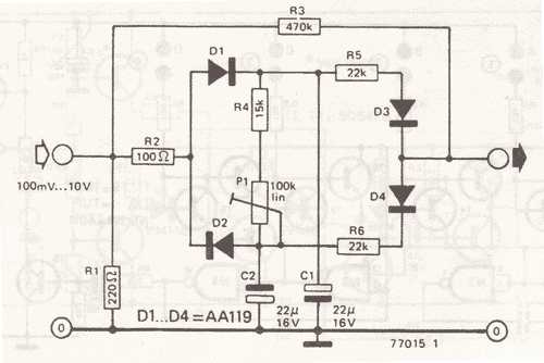

he AA119 diodes used in the original schematic are germanium type, which will have a turn-on voltage that is about half that of the 1N4148 diodes that you are using. They also have a longer knee range. These two specs will significantly change how the compressor reacts.
Enter your email address to join: