EZ Tube Mixer Support Thread

GroupDIY Audio Forum

Help Support GroupDIY Audio Forum:

This site may earn a commission from merchant affiliate links, including eBay, Amazon, and others.
ramshackles said:
Elma has some pretty good resources on eurocard specs & dimensions if you are interested:
http://www.elma.com/services/us-resources/eurocard-specs/

I was wondering if you know whether it would be possible to mount a PCB at 90 degress to a eurocard, along the front plate in order to mount switches/pots etc and associated components (i.e for switched volume controls) ? Could it be fixed using the same brackets that fix the eurocard to the front plate?

I don't see why not, you probably can use cheaper generic brackets. You will probably need to drill the pcb as well. Maybe have it fixed to the front plate instead with risers....How will you connect the daughter board to the main board?

Thanks for the link,

Pierre
 
Daughter board to main board...depends what the board is, but either just wire connections or terminals/headers. On most of Ians boards it seems there is a gap between where the brackets go and components end. Certainly enough for a PCB to slot across.
 
anjing said:
For the crimper i have a similar one, i did a lot of research on the subject and it seems that the quality of crimper makes a big difference. The one from molex costs the price of several transformers! 

Regards,

Pierre

I agree. The one I have has a ratchet action that only releases when you have completed the crimp properly. The very cheap types with the red handles are no good at all. I think people mainly use them for faston connectors.

Cheers

Ian
 
ramshackles said:
Daughter board to main board...depends what the board is, but either just wire connections or terminals/headers. On most of Ians boards it seems there is a gap between where the brackets go and components end. Certainly enough for a PCB to slot across.

I try to leave a  gap free of tall components on the PCB behind the front panel for exactly that reason. There's a lot of hand wring in a module, both between the main board and the eq and from the eq PCB to its controls and also from the main board to the pan and aux controls. The benefit of this method is infinite flexibility - you can build any sort of module you like with the controls placed anywhere you like. The disadvantage is of course it takes a lot of effort to wire it all up and it is easy to make mistakes.

I have been thinking about ways to simplify module assembly and some extra PCBs is certainly one way to go. The smart pan is an obvious candidate and I think others have already made a PCB for this.

EQ connections can also be numerous. The Helios EQ is not two bad as it only has two pots and ttwo switches. The REDD EQ is OK as three of the switcehs are on the PCB and the other fits to a ribbon cable. The real PITA is the 3 band Pultec which has six pots and two switches to wire up. They fall into two groups of physically close three so a 10 way ribbon connected to each mating with an pot PCB seems like a possibility.

At some point I may well design a set of 6U high PCBs each of which contains the mic pre and one of the three EQs with all panel mounted controls brought out to headers - but that's a long way off.

Cheers

Ian
 
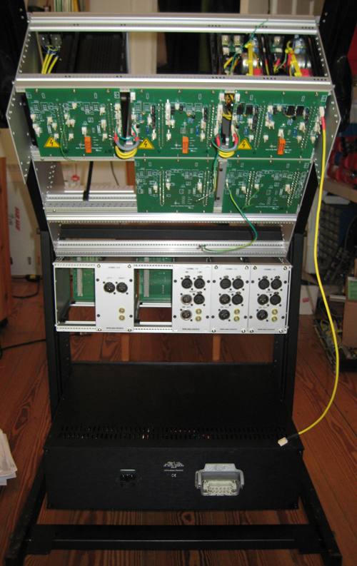
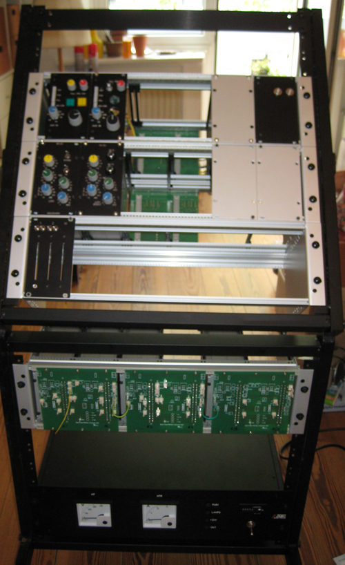
I've found an old 19" trolley in my attic today and decided to use it for my feasibility study.

rack2.jpg


rack1.jpg


Some noise figures with two channels:
Signal in 6 dBu, Gain/fader set to ~6 dBu at direct out.
Noise pre fader at direct out: -90 dBu, post fader/EQ -83 dBu.
Stereo bus is at -83 dBu fader at +6 dBu position.
Edit: it's at -80 dBu, measurement error. It's OK but could be a bit better.
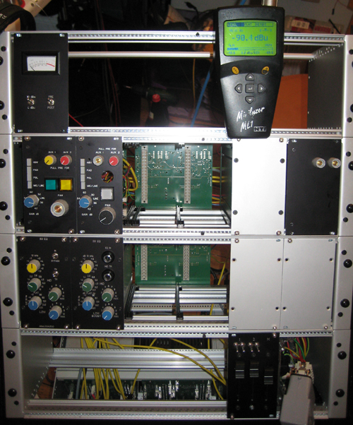
I need more channels...

racks3.jpg
 
Holger said:
More modularity: second EQ with slightly improved front panel design, still not final.
Do you guys prefer the toggle switche version or the other one?

holger where did you get the plastic insert switches from as i need some spares for a Siemens c4 mixer im servicing
 
I'm still experimenting with the console frame prototype so while waiting for components i decided to tackle the arm rest.
Arm1-2.jpg

Arm1-3.jpg
 
I just finished a new stereo line in module using the twin line card. The two cinemag CMLI-15b that i tough were the wrong footprint fit in the wholes for the jensen transformer.
Sounds very good!
Seems i have more gain then my other mono modules even with the gain trimmers at the lowest level.
I pierced a whole to fix the cables for the volume pot and for the connection to the stereo bus. I wanted to drill in the plastic and not the ground plane. I'm a bit to close to the back plane! The next module i will probably drill the front of the pcb, near the front plate.
TwinLine-3.jpg
 
anjing said:
I just finished a new stereo line in module using the twin line card. The two cinemag CMLI-15b that i tough were the wrong footprint fit in the wholes for the jensen transformer.
Sounds very good!
Seems i have more gain then my other mono modules even with the gain trimmers at the lowest level.

The mono modules have a 33dB attenuator followed by 20dB gain from the mic transformer so the input level to the amp is -13dB and the 33dB setting of the gain switch gives an overall unity gain (20dB from the transformer and 13dB from the amp).

On the Twin Line Amp (TLA) you go through a 1:1 transformer so the input level at the amp will be 13dB higher than in the mono amp case. Even with no gain trim pot, the TLA gain is 6dB so the output is higher than the input. With a 10K trimpot set to 10K the gain will be about 15dB so it is no wonder your outputs are rather higher than expected. If you have a fader after the transformer then you might want it to have 10dB in hand so you would need to set the gain to about 10dB. A gain resistor of about 39K will set the TLA gain to close to 10dB. If you want to retain a trimpot then it would be better to use a 50K or 47K linear one but even then the 10dB setting will be at about 80% rotation.

Hope that helps.


Cheers

Ian
 
Thanks Ian! I found the problem! I forgot the bus resistors for the twin channel....now it's better.
If i understand correctly the pultec has around 20db loss so i should be ok with the 10k trimmer as i have now...

Regards,

Pierre
 
anjing said:
Thanks Ian! I found the problem! I forgot the bus resistors for the twin channel....now it's better.
If i understand correctly the pultec has around 20db loss so i should be ok with the 10k trimmer as i have now...

Regards,

Pierre

That is correct. The 10K trimmer gives 20dB gain at close to the half way point.

Cheers

Ian
 
Good progress, Pierre.

I've reconceived my grounding scheme and I'm using a Rittal grounding bar as star ground now. I furthermore found that my 12V for relay switching adds too much noise, I need a new solution here.
So currently I only have post fader direct outputs because I removed the 12V rail.
I've improved my noise floor numbers. Direct out (post fader/EQ) of the channels are at -87 dBU. The best is my L/R master out:  -87 dBu when feeding my two channels to the stereo bus (fader set to 6 dBU output level position when signal is applied).
That's 7 dB less noise compared to my old grounding scheme. I'm confident now that it is possible to build a bigger mixer.


Attachments

  • Bildschirmfoto 2013-08-10 um 18.38.30.jpg
    Bildschirmfoto 2013-08-10 um 18.38.30.jpg
    22.5 KB · Views: 45
Hi Holger,
  Were do you put your grounding bar?
The angle of the connectors indicate the backplane for your in & out modules?
I just bough an minilyser second hand to qualibrate the gain troughout  the console.
I'll be able to compare numbers with you as well.
It's good news about the possibility of a bigger mixer with all the work you put in already.

Regards,

Pierre
 
Holger said:
Good progress, Pierre.

I've reconceived my grounding scheme and I'm using a Rittal grounding bar as star ground now. I furthermore found that my 12V for relay switching adds too much noise, I need a new solution here.

That is an interesting comment Holger. Is this switching noise you are referring to or is it more general noise picked up by the audio path through the relay?

Cheers

Ian
 
The 12V noise was added by my SMPS.
My idea was to use a 3.5A SMPS for relays and lamps. After unconnecting this 12V rail from my backplane I found that my audio path was much cleaner. Today I set my JLM linear PSU to 12V and connected it to my backplane: no additional noise.

Edit:
measurements of the master bus noise floor: -87dBu with linear supply, -78dBu with SMPS


Back
Top