micah421 said:
The Main board connections (+15v,-15v, 0v, L, R, Ret) seem to be working. That sends and returns the audio path and feeds power the SSC board power, correct or am I wrong?
What is the AC voltage at differential line receiver NE5534-pin6 on main board with an audio test signal connected to one (L or R, not both) of the XLR-input connectors? Maybe 1.23VAC as an example value (we have no idea of your secret test frequency amplitude). Note this number.
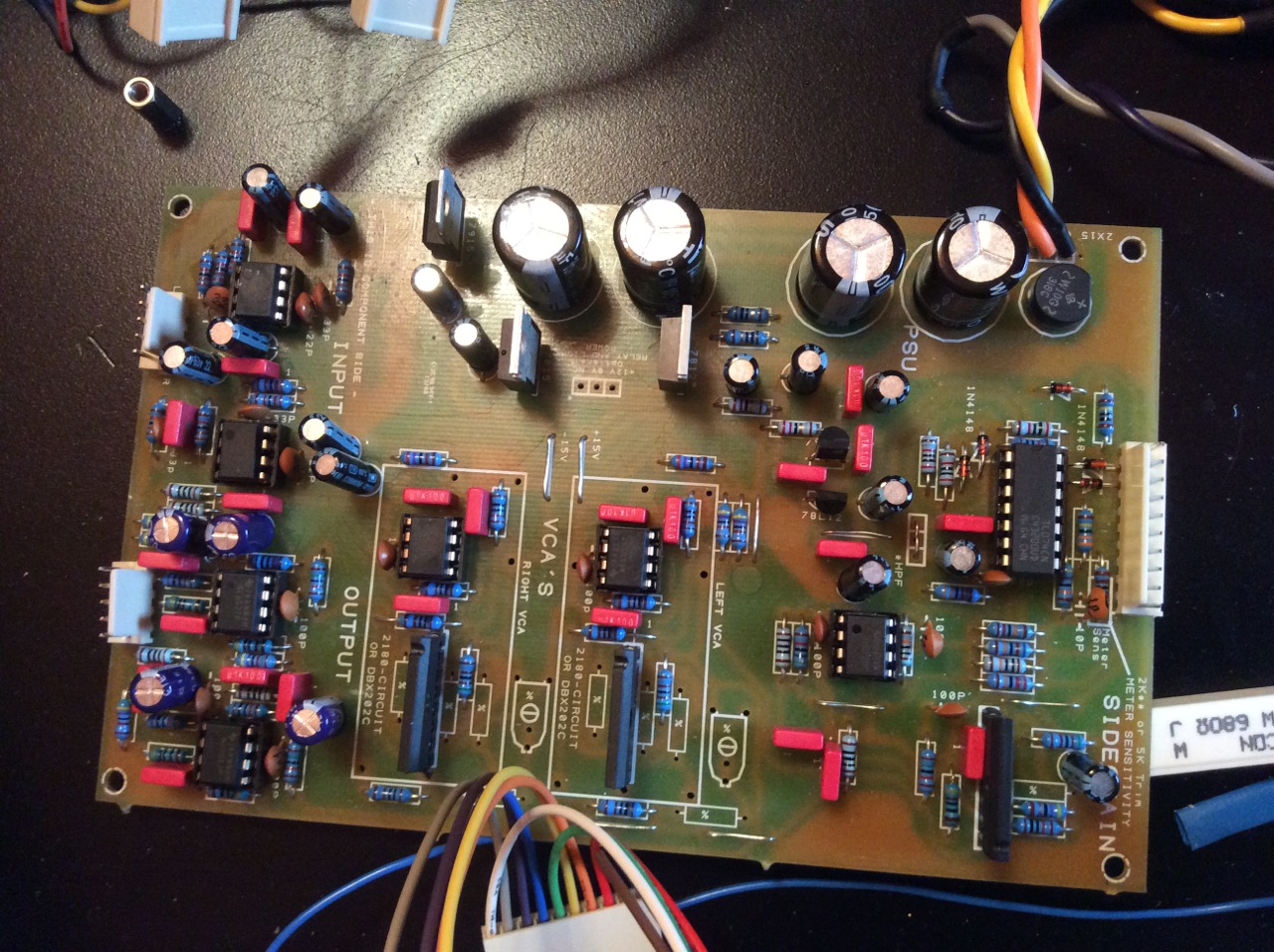
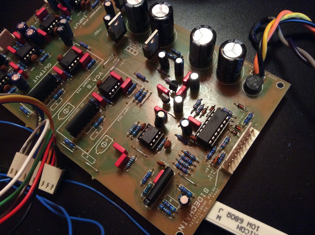
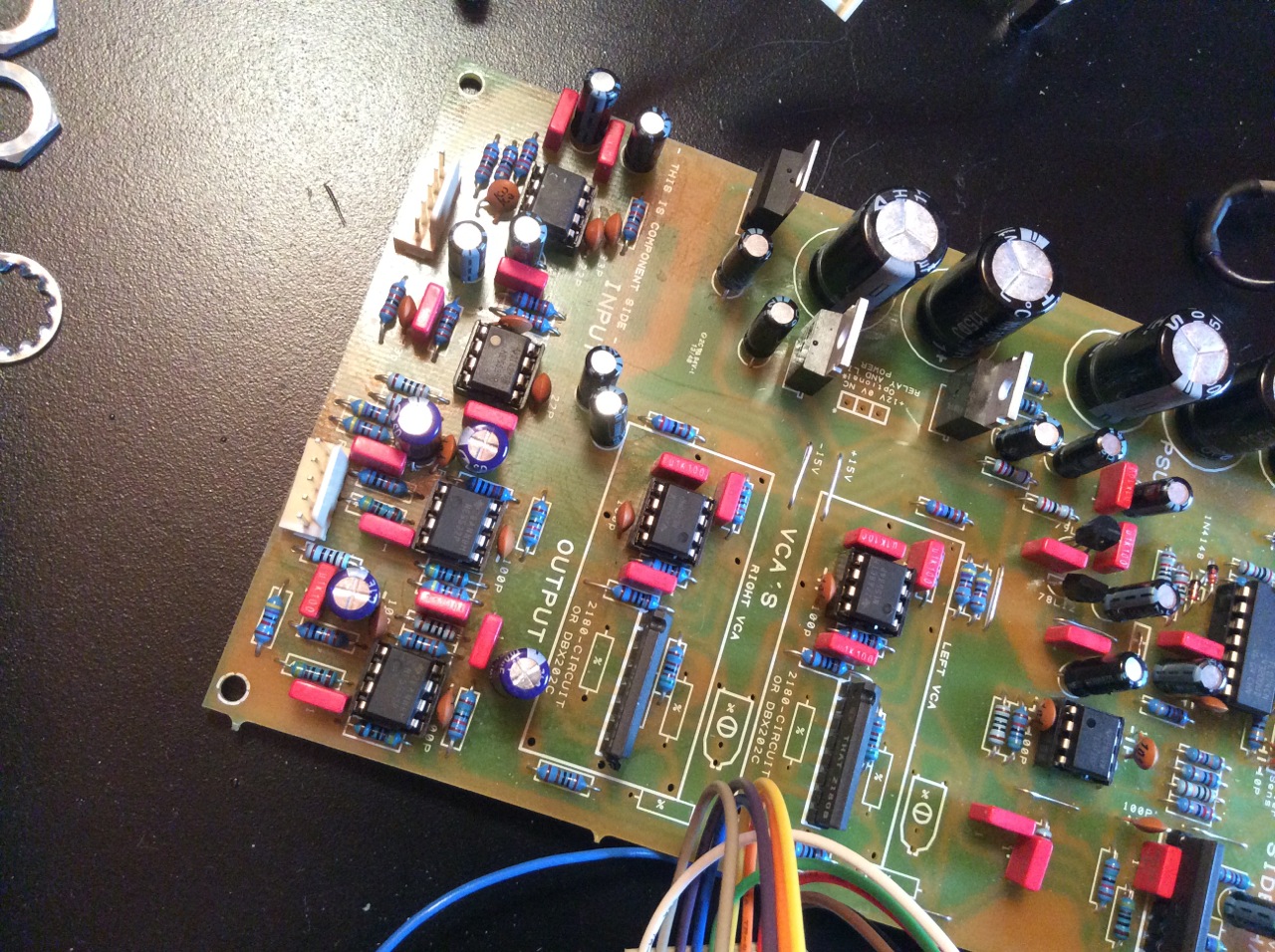
You removed the 47K summing resistors on main board that get substituted by your filter board ? ('super sidechain' is the least important part of the boards name).
What is the AC voltage at SSCF board next to input connector NE5532-pin7? Is this readout about half the value of previous example readout=0.615VAC?
Yes? Move on, else check why signal doesn't arrive here. (Broken wire, broken pcb trace, broken opamp, opamp not pushed into its socket, opamp missing power supply DC voltages at pin4 and 8, wrong resistor values, ...)
Depending on frequency of your test signal and lorlin switch filter setting (we have no idea of your secret test frequency number and the purpose of this filter board is to decrease the signal amplitude below the selected HPF cutoff with a -6dB/oct.slope), same or slightly lower AC voltage as previous measurement should show up on your lorlin switch pole.
Yes? Move on, else check why your lorlin switch doesn't connect.
Same AC voltage as previous measurement should show up on same (the opamp located next to SSCF input connector) NE5532-pin1.
Yes? Move on, else check for wrong 12K resistor values.
SSCF output connects to the right side (VCA side) of the removed 47K resistors on main board ?
With 1kHz signal feed and lorlin switch set for position TL, measure AC voltage as described in 1st step and adjust TL trimmer for half this measured readout.
With lorlin switch set for position TM adjust TM trimmer for same readout.
Disconnect XLR-input connector and plug it to the other input to check for same readout of last TM measurement in order to prove both sides behave the same.
Done.
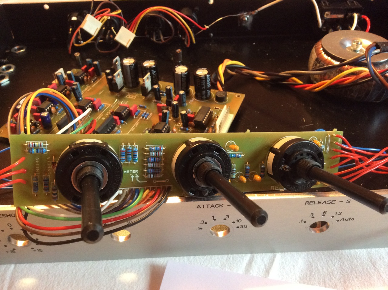
I thought the COM, ON, OFF, POTA, POTB section deals with the Threshold, Ratio, Attack, Release controls.
In no way. All connections are for the substitution of the original lorlin bypass switch.


")