GSSL HELP THREAD!!!

GroupDIY Audio Forum

Help Support GroupDIY Audio Forum:

This site may earn a commission from merchant affiliate links, including eBay, Amazon, and others.
Hello, hope I am posting in the correct place!  :)

I have got my GSSL up and running, sounds very nice and works fine however I have encountered a few problems.

I should also say that I have the Expat Audio VU Driver installed, which I believe works fine too.

The first problem is that even though I can achieve compression, which shows on the VU meter and is obviously audible, changing the ratio makes no difference at all. I understand that lowering the ratio will also lower the threshold. So basically the ratio doesn't seem to work.

The second and hopefully final problem is that as I change the attack and release the pointer on my VU meter moves towards the left and right (depending on the settings of attack and release). It is only on 0dB when the settings are at 10 on the attack and .1 on the release. I think this is because when I powered up the unit the meter was pointing to -3dB so I corrected it to 0 using the trim pot on the VU driver board and these where the attack and release settings at that time.

Thanks for your time!

Jeremy.
 
Sorry for not answering you Jeremy, I have another question that is less technical.
I am working on my faceplate right now, is unity gain achieved when make up pot is fully CCW? or somewhere in the first half?
(In other terms, my graduation will be either 0 > +20dB or -5dB > 15dB)
 
Turn your makeup gain all the way CCW while running audio through it. Now put the unit in bypass. Did the volume  decrease or did it stay the same? That would give you your answer...

And a quote from Gyraf's site: Make-up gain: 0 to 20dB adjustable.
 
Yep, thanks, so many many -5 to +15dB faceplates got me into doubts.
I have finished the build yet but for schedule reasons I need to get going on the faceplate and finish it ASAP

Will keep you guys posted!
 
Any thing I should be aware of if choosing stepped version from pcbgrinder
https://pcbgrinder.com/index.php?route=product/product&path=60&product_id=50
?

Is it pcb-stepped or handsoldered stepped pots?
Is it stepped for all pots?
 
G-Sun said:
Any thing I should be aware of if choosing stepped version from pcbgrinder
https://pcbgrinder.com/index.php?route=product/product&path=60&product_id=50
?

Is it pcb-stepped or handsoldered stepped pots?
Is it stepped for all pots?

"Option of detented potentiometers for Threshold and Gain recovery."

The rest of the controls are on stepped switches already (check the project info).

My mail is always open for this kind of thing :)

Gustav
 
What is the range of the threshold and makup-gain pots?

Any recommendations regarding stepped vs. pots?
I'd like to have correct values on frontpanel if stepped. And I need to choose either just 11x4,7ohm (right?) or adjust for what is exact db or most useable.
 
G-Sun said:
What is the range of the threshold and makup-gain pots?

Any recommendations regarding stepped vs. pots?

I'd like to have correct values on frontpanel if stepped. And I need to choose either just 11x4,7ohm (right?) or adjust for what is exact db or most useable.


I put some detented pots on my site a few weeks ago, and this seems to have caught your attention. I have not heard of a single instance of a GssL being built with detented pots or switches replacing the makeup gain/threshold controls, and the project is more than 10 years old. Its more of a gimmick, a little something added, but not essential.

The potentiometer is 50K(47K) range, and there are 11 "clicks" in the detented pot. You can do the same with a switch (Any numbers of steps you wish), if you figure out which resistor values to use for an even step sequence, or you can use a free floating potentiometer.

The first two makes critical recalls easier, but would not add anything to the sound.

There is 20dB make-up gain present in the GssL. Threshold would be dependent on the amplitude of the input (I am not sure if theres an absolute way to denote this function), and I would simply number both controls 1-11 for recall.

The 50K/47K pots are both linear, but I dont know if a linear sequence of steps (4,7Ohm, you probably mean Kohm), would give you a functional, linear amplitude throughout the range of the switch. If I really wanted the function, I would try it and ask what I was doing wrong, if there was a problem.

Dont be afraid to use my e-mail, if you still have questions that are more geared towards making a decision on what to build rather than actual trouble shooting :)

Gustav
 
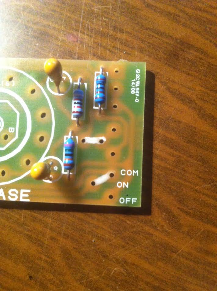
Can someone tell me which points of the control board I should strap together if I want the comp to be on all the time (hard bypass with relays)?
Should I simply strap points according to Gustav's website building instructions following wire of the same colors (not sure of how the switch works tho) or is there a more elegant way of doing this?

Thanks in advance

Thomas

Edit: is this correct? (link where white pen)

 
thomasdf said:
Edit: is this correct? (link where white pen)

Didn't check with the board, but looks right.

And whats the worst that can happen if its not?

Gustav
 
ctechdx said:
Hello my friends...

Please, helpe me with that question.

Why WIMA capacitors are the most used for audio equipment? I read some things about it, and some people say that wima capacitors sounds amazing, and I see their are used on some of the best high-end audio gear on market. Then I would like to know more about... if someone did compare it, and if it will really make a considerable diference at my compressor´s sound.

I will start to build my GSSL probably next week... for the moment I got VISHAY´s polyester capacitors. This one:

http://www.farnellnewark.com.br/capacitorpolyfilmfilm01uf563vfullreelproduct,product,27X7657,0.aspx

Should be better to change for wima capacitors? Can I change other capacitor in this project for WIMAs, like the ceramics and tantalum capacitors? I´m asking this coz I cannot find wima capcitors in brazil, but I have to buy the THAT´s VCA from mousers and I could buy the wimas togheter if it makes a considerable diference.

Please I would like to have some thoughts about it.

Thanks,

Deja Vu?

http://groupdiy.com/index.php?topic=47.msg727820#msg727820

Use tantalums and ceramics where specified, and do not worry too much about brands. It will have the familiar VCA compression characteristic, even if your decoupling caps are not WIMA.

I feel strongly that doing things in steps would yield a much greater success rate in DIY. You are learning how to select components now, and when you have the items on your bench, you will learn something about soldering and building a compressor. Worrying about the sound of different capacitors (especially with none of them in the signal path) is like shopping for cycling gloves that will shave .1 seconds off your time on your first trip 100km, when you dont even know if you can put together your bike yet.

(My first cycling analogi, so it may not make sense :) )

Gustav
 
Hello everybody, I am having some troubles with the sidechain of the compressor so I hope you can help me.

The main board works fine as I have a signal in and out of the compressor, the power switch and the bypass are working too, but I don't get anything from the control panel (including VU meter, threshold, attack, release and make up). I only get a clipping sound when I turn the ratio/attack/release, the VU meter is still at 0dB with a small variation when I change the ratio.

It is weird because the THAT2181 and TL074 are working well and I checked the 10 way connectors too. I also have the +12V/-12V where it should be on the control board. Any ideas ?
 
Tritriren said:
Hello everybody, I am having some troubles with the sidechain of the compressor so I hope you can help me.

The main board works fine as I have a signal in and out of the compressor, the power switch and the bypass are working too, but I don't get anything from the control panel (including VU meter, threshold, attack, release and make up). I only get a clipping sound when I turn the ratio/attack/release, the VU meter is still at 0dB with a small variation when I change the ratio.

It is weird because the THAT2181 and TL074 are working well and I checked the 10 way connectors too. I also have the +12V/-12V where it should be on the control board. Any ideas ?

did you solder the jumper on the hpf connection?
 
edit : I did put the jumper next to the + meter on the control board and also in the hpf connection. I changed the pots and the 10 way molex. I still have some clipping while using the ratio/attack/release and the VU meter is going up past 20dB when I activate the compressor.
 
Tritriren said:
edit : I did put the jumper next to the + meter on the control board and also in the hpf connection. I changed the pots and the 10 way molex. I still have some clipping while using the ratio/attack/release and the VU meter is going up past 20dB when I activate the compressor.

I can't really tell if the controls are not working at all, if they are working, but with some slight clipping, if they might be working perfectly, but you're feeding the compressor a very hot signal (or even if you reversed the meter).

In an earlier post, you mentioned that everything works (even bypass) expect for the control board, but the bypass is on the control board. To clear up such issues, it would also be nice to know if you did anything that strays from the "typical" Gyraf configuration (I am a big fan of pictures, others may not care).

Gustav
 
ctechdx said:
I would like to have some suggestions for those two square switches for the front panel. Which one you guys normaly use for this project? Preferably I want something that I can find at mouser.
Also suggestions for diferents switches and diferent shapes are welcome... I´m open for suggestions.

NRG pushbuttons: http://www.frontpanels.de

image.jpg


EAO (used by ssl): http://ca.mouser.com/ProductDetail/EAO/01-281025/?qs=%2fha2pyFaduhahYtYs%2fNq8%252berrxl2aP69OhAhkGq2m8uSfiZaduXiwA%3d%3d

NKK: http://ca.mouser.com/ProductDetail/NKK-Switches/UB25KKW01N-E/?qs=sGAEpiMZZMvxtGF7dlGNpnVK9G1xXedU24MBiUbJrNY%3d
 
Gustav said:
I can't really tell if the controls are not working at all, if they are working, but with some slight clipping, if they might be working perfectly, but you're feeding the compressor a very hot signal (or even if you reversed the meter).

In an earlier post, you mentioned that everything works (even bypass) expect for the control board, but the bypass is on the control board. To clear up such issues, it would also be nice to know if you did anything that strays from the "typical" Gyraf configuration (I am a big fan of pictures, others may not care).

Gustav

Sorry for the late answer.

My compressor is built according to the assembly guide on the mic & mod website. The only thing I changed was a head sink on the top of the 7815 because it was abnormally hot.
I went back to the 10 way molex which seems to work fine. As you said, the clipping and reaction of the VU meter might be a "good" sign that the control board is working but I can't put on my finger on what's wrong.
I'll post some photos of the back of the control board as soon as possible.
Thanks again !
 
ctechdx said:
Guys, please, how many poles I need on the bypass toggle switch? I´m looking for this one... single pole... would work for the gssl bypass?

http://www.mouser.com/Search/ProductDetail.aspx?qs=O%252b9txF4fliQQrrqL05EWDA%3d%3d

thanks,

You need a DPDT on-on switch, and make sure to check its not a non-latching type.  (If you check the PCB drawing or any other documentation to see how the switch is soldered, you will see it needs two poles and two positions).

Gustav
 
ctechdx said:
Thanks Gustav.

For the power switch I´m taking a illuminated rocker switch DPST 16A ON - OFF. Is this ok for the job? Please, if you can... take a look...

http://www.mouser.com/Search/ProductDetail.aspx?R=CN202J3RS215Q8virtualkey61170000virtualkey611-CN202J3RS215Q8

It would work.

ctechdx said:
And a final question...

I have some IC sockets turned pins here... like this one:

https://www.baudaeletronica.com.br/media/catalog/product/cache/1/image/650x/040ec09b1e35df139433887a97daa66f/1/6/16_pinos.jpg

If I split this socket in two parts can I use it for the THAT2180 or it´s a diferent socket?

Thanks for all your help.

Best regards from Brazil,

Yes, that would work.

Gustav
 

Latest posts

Back
Top