Input impedance of G1176 with OEP-TX (1+1:6.45+6.45)

GroupDIY Audio Forum

Help Support GroupDIY Audio Forum:

This site may earn a commission from merchant affiliate links, including eBay, Amazon, and others.
mnats, what did you think of the sound with the A262A2E in there? I just recieved mine from Newark today, and am hoping it sounds cool. Oh well, it's not too much money lost if I don't like them.

Now...if I could just figure out how to wire this thing up. I'm using Gustav's old boards that don't have the OEP's as an option. Anybody have any input on this. I kind of looked it over a little...and so far I don't really understand which pins go where on Gustav's boards (meaning where do the OEP's correspond with the pins on gustav's boards?)
 
I'm having trouble finding the data sheet for the OEP, that's half my problem. The only info I can find is this:

http://www.oep.co.uk/audio_transformers_high_performance/audio_transformers_high_performance.html

I'm not sure if that has all the info I need. If it does, I'm not sure how to read what I'm looking at. They label the pins S1 S2 and F1 F2 things like that. S maybe means secondary? F means?? And then both sides of the transformer have pins that are identically named...which confuses me even further. I don't know what's up and down when looking at this thing. Newark doesn't seem to have the datasheet posted either.

Any help would be most appreciated.

Thanks,

Jay
 
S=start F=Finish of windings - to indicate winding polarity.

Pri and sec are noted over/under the drawing. Use ground pin for orientation.

Jakob E.
 
You'll have to forgive me, this is the first time I've had to wire up an audio transformer. I'm obviously missing some crucial bit of info to help me. Here's where I'm at.

I want this wired up for the higher gain.

1. I don't know if I need 150ohm from the 1176 circuit to the output transformer, or 600ohms. I don't know if I should have the output be 600ohms or 2.4kohms.

2. On the input transformer again, same thing. I'm assuming I want the input into the transformer to be 600ohm, and the output to be? I don't know. I can't figure it out by the schematic. I'm not knowledable enough to do that.

3. I'm not sure how to wire these in series and parallel. Here's what would make sense to me. To wire in series I connect S2 to F1? To connect them in parralel, I connect S1 to S2 and F1 to F2? That seems correct in my head anyway. Then I connect Screen to ground, correct???

4. Once I figure this part out, I think I can get it connected to the board based off of the schematic, but would appreciate it if someone here would look over my work to ensure that I've got it right before I wire it up.

Hopefully someone can help me connect the missing dots this time, and then next time I'll be able to figure it out on my own. When I built the GSSL, someone helped wire up the power transformer, and now with the G1176 I was able to figure it out by myself. Big steps...I know. :wink:

Thanks again,

Jay
 
Hi Jay,

Basically you want to make the A262A2E (which is a 1:2 transformer Pri:Sec) into a 1:1 transformer at the input, and a 1:2 at the output.

Here's possibly the clearest OEP Datasheet PDF

And here's the basic pinout of the A262A2E:

A262A2E_pinout.jpg


The input side looks like this:

A262A2E_1176_input.jpg


And the output like this:

A262A2E_1176_output.jpg


Note that the diagrams are viewed from above the transformer. Connect the screen to 0V/Gnd.

Hope this helps!

Mark
 
BTW,

In your points 1 and 2 above, you mention the impedance matching. A transformer has no inherent impedance (apart from DC resistance and inductance), but it reflects an impedance from primary to secondary and vice-versa.

The impedance ratio is the square of the winding ratio. So on the datasheet for the A262A2E it shows the impedance for series and parallel connections. This assumes a certain termination, which is then reflected to the square of the turns (winding) ratio- e.g. 1:2 would be 600R:2k4 (2k4= 600R*2^2)...but this assumes one side of the transformer is terminated by a 600R resistor at the primary or a 2k4 at the secondary.

In the G1176, with a 1:1 input transformer (e.g. the OEP connected as above) the input impedance is basically 10k (the value of the input pot) This isn't exact in practice- but it's near enough.

The output transformer is a step-up of 1:2, so the output impedance is actually four times the output impedance of the driver amp. But in practice (I've wired quite a few G1176's 1:2- the "Swedish Chef" mod- and haven't had any problems other than the noisefloor being increased by +6dB. Some extra grounding helped this...)

Anyway, good luck with your mods. I actually like the sound of the OEPs too!

:thumb:

Mark
 
Thank you for the help and explanation Mark!!

Okay, here come a couple REALLY stupid questions...but I have to ask because I don't get it.

I think what's getting me are the ratios (1+1:6.3+6.3 or whatever it may be). Do those numbesr represent an increase or decrease in power and impedance, depending on the ratio?

The way I see it in my head (obviously incorrectly) is that I want to see the start of each winding be equal to 1. I don't understand how it could not be. Isn't it the winding of coils that either increases or decreases the voltage? I mean at the input to the windings, there could be no change, right?

So, then I see an oep like a 6.3+6.3:1+1. Is it just intended to be a step down transformer and they label it that way? I don't know, I don't get it. How can the input be represented by the number of a 6.3 ratio? Is it just because they don't want it to be represented by a negative number and say 1+1:-6.3:-6.3?

Looking at your input figure. The transformer is a 1+1:2+2 transformer. So, you connect the end of one winding to the front of the other. That doubles the length of the coil. Then on the other side you take start of both windings and tie them, and the finish of both ends and tie them. What does this part of it do for you. I guess I don't understand why wiring the output (input diagram) in parallel like that = 1:1?

Have I made this too confusing?

Thanks again VERY much for the help!!!! :guinness: :guinness:
 
> Do those numbers represent an increase or decrease in power....?

In a transformer, power out EQUALS power in. (Neglecting a little loss, which is usually negligible.)

A transformer can NOT increase Power. It will always waste some power, but usually very little.

The funny numbers say what happens to Volts. And to make the power=power thing work out, the Current is changed by the same number but the other way. The product of Volts time Amps (Power) stays constant (neglecting loss). The ratio of Voltage divided-by Current (Impedance) is changed, by the square of the turns-ratio.

Take a 1:2 transformer. Put 1V on the input. The output is 2V.

Say you put a 1Ω load on the output. It takes 2V/1Ω= 2 Amps. (2V/2A=1Ω.) The Power is 2V*2A= 4 Watts.

If 4W is coming out, 4W must be going in.

If the input voltage is 1V, then the input current has to be 4A: 1V*4A= 4W.

Or knowing that the turns-ratio (voltage ratio) is 1:2, then we know the current ratio must be 2:1. So the input current must be twice the output current. 2A output current times 2= 4A input current.

Now we know the input is 1V/4A= 0.25Ω, the output is 2V/2A= 1Ω. The impedance ratio is 0.25Ω/1Ω= 1:4. That is also the square of the turns-ratio (or the voltage-ratio). Since power is not changed, when voltage goes up by 2 then current goes down by 2, so voltage/current (impedance) changes by 4.

Or put 10KΩ on the output of a 1:2 transformer. The impedance ratio is 1:4. So with output loaded in 10KΩ, the input looks like 10KΩ/4= 2,500Ω.

In this FET-limiter we have a line level input of around 1 Volt, and an FET that will distort with more than 0.010 volts. So we really want a step-DOWN. Use a 2:1 transformer. I don't have the plan handy; assume the input to the resistor and FET looks like 10KΩ. Then the input side of the 2:1 transformer will want to be 10KΩ*4, or 40KΩ. (It won't really be that high due to losses we ignored. And we'll continue to ignore them because in 600Ω systems it makes no difference if the actual input impedance is 40KΩ or 4KΩ or even somewhat lower, as long as it is well above 600Ω.)

In real use, the input comes from a preamp or mixer with an output impedance of maybe 600Ω. After the 2:1 step-down, this looks like 150Ω. In the 1176 this is unimportant. The 150Ω means large current is available, but a resistor-FET limiter does not need large current, won't take large current. But if instead we were driving a diode attenuator, we might use series resistor like 1KΩ and need a driving impedance much lower than 1KΩ; 150Ω is much lower than 1KΩ so we'd really need the step-down to get the necessary impedance.

> on the other side you take start of both windings and tie them, and the finish of both ends and tie them. What does this part of it do for you. I guess I don't understand why wiring the output (input diagram) in parallel like that = 1:1?

It will work nearly the same if you just use one coil. You still get a 2:1 ratio.

Now we get into losses. There is resistance in the copper wire in each coil. If you design a transformer for one specific ratio, you use two coils each filling half of the available space. But it is convenient to wind 4 coils that can be connected several ways, to get different ratios out of one standard part. If you used just 3 of the 4 coils, you are only using 3/4 of the copper that fits on the core, and your resistance loss is about 4/3 times higher than necessary. In some circuits this will cause a small but measurable loss of level. In the 1176 I don't think the added copper loss from using just one of the two secondary windings will matter one bit.

But there is another issue. In an iron-core transformer, 99.9% of the magnetic flux goes through the iron and therefore jiggles all coils on the core. But about 0.1% of the flux goes through the air, and half of that misses other coils on the same core. That acts as a small inductance that increases output impedance at the top of the audio band. If loaded in something near design impedance, extra leakage inductance rolls-off the highs. By using four coils with primaries between secondaries, we get less leakage, better coupling. Not using one of the four coils means increased leakage. But again, the 1176 loads the tranny so lightly that this may not matter.

There is one more reason to always parallel two coils when you can. The most common failure in transformers is a broken winding wire: pinch in winding and stressed by temperature, or moisture gets in and rots the copper. Ideally, we'd use fewer windings of fatter copper to reduce this problem. But given a 4-winding tranny, if you do parallel when you can then the tranny will keep working even if one of those two parallel windings fails. It won't meet exact specs with a failed winding, but it won't knock you off the air, and the added loss may never be noticed.
 
Wow, thank you PRR! That's a lot to digest. I keep intending to take a class to get the basics, but things keep coming up. It sometimes feels like I'm in the vaccum of space with no bearings, trying fly blindly back to Earth.

I read what you wrote about 3 times, and the math seems simple enough, it's just my understanding of the really basic stuff that needs some working out. I've always used watts and volts pretty interchangably (in my thought process). I just read some basic ohms law stuff, and think I'm starting to get it. I'm not there though. It's so simple on paper, but how to use it in application, is where I get lost.

So ohms law is:
Resistance = Voltage / Current

What that means in a circuit is beyond me. So say I have an opamp that is looking for 12v. I have 30v. How does ohms law get me down to 12v? I know I have A, which is my volts (30v), B which is my desired voltage (12v) and C the resistence needed to get me to 12v (which is unknown). I'm guessing there's a different formula for this?

Anyway, this is all helping a lot. I'm pretty green with this stuff (obviously) so thanks for the patience and help!
 
I think I've got the windings figured out, and how to install the transformers. Will someone just double check me to make sure I've got this right?

Here's the Lundahl ll5402 transformer pinout for the output of the G1176:

Lundahlll5402drawing.jpg


Here's the OEP A262A2E replacement:

A262A2E_pinout.jpg


Here's how they match up for the primary windings:

OEP Lundahl

S1 = pin 1
S2 = pin 5
F1 = pin 2
F2 = pin 4

Here's how they match up on the secondary windings:

OEP Lundahl

S1 = pin 6
S2 = pin 10
F1 = pin 7
F2 = pin 9

Those Lundahl pins correspond to the numbers listed on the Jakob's PCB for the G1176. Right?

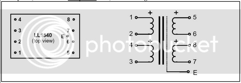
So now let's do the input transformer. For that we are replacing the Lundahl LL1540 with the OEP A262A2E (which is the same transformer we used on the input).

Here's the Lundahl ll1540 transformer pinout:

LundahlLL1540drawing.jpg


Here's the OEP A262A2E replacement:

A262A2E_pinout.jpg


Here's how they match up for the primary windings:

EDIT! I removed the pinouts, because as Mark points out, they do not correspond correctly because this transformer is wired totally different than the Lundahl.

And again, when installing this, these pin numbers should correspond to the numbers on Jakob's PCB for the G1176. Do I have all of this correct?

Also, I'm assuming that the point marked as "*1" on the PCB is where I should connect the input pot, as opposed the point marked as just "1" because I'm using the input transformer.

Thank you,

Jay Lison
 
Also, I'm assuming that the point marked as "*1" on the PCB is where I should connect the input pot, as opposed the point marked as just "1" because I'm using the input transformer.

Yes, I have had the same question regarding the 1* pin. I was wondering whether you can jumper the 1* to the regular 1 pin via the connection that would have been the 6.8uf cap of the regular balanced input section. I was looking at the PCB and saw that the regular 1 pin is connected to that. Then you would just run the 1, 2, and 3 pins to the input pot. It seems a little tidier than running 2 shielded wires from the PCB to the input pot.

There is also a unused ground connection nearby where you could attach the shield from the jumper (if you used shielded wire) and just leave the other end unattached using heat shrinking to protect it.
 
> say I have an opamp that is looking for 12v. I have 30v. How does ohms law get me down to 12v? I know I have A, which is my volts (30v), B which is my desired voltage (12v) and C the resistance needed to get me to 12v (which is unknown). I'm guessing there's a different formula for this?

Opamps are not perfect resistors! You will get in trouble thinking this way.

Light bulbs are not perfect resistors either, but ignoring some start-up glitch we can pretend they are.

You have a 30V battery. You have a 12 Volt light bulb. What resistor is needed to make the lamp happy?

Answer: Can't say. Insufficient data given.

OK, You have a 30V battery. You have a 12 Volt 1 AMP light bulb. What resistor is needed to make the lamp happy? This problem CAN be solved.

> I've always used watts and volts pretty interchangeably

Watts is like you have a ton of lead that has to be moved 10 feet upstairs every hour. It is real work.

Say you decide to use a water wheel to turn the winch to lift the lead. You have a dam with the lake on the upstream side 10 feet higher than the waterbed on the downstream side. Can you extract enough water-power to lift your ton of lead upstairs every hour?

Answer: Can't say. Insufficient data given. How much water goes over the dam? A million gallons a second? One drop per day? Makes a big difference.

In fact there is a direct answer. You need to lift 2,000 pounds 10 feet every hour. You need the same total weight and fall of water to do the job. It could be 2,000 pounds water every hour falling 10 feet, or 20,000 pounds falling 1 foot, or 1 pound falling 20,000 feet. All represent the same amount of work available, but these require very different water wheels.

If we use the height of the fall as "voltage", then the "width" of the water (how many pounds per hour) is "current". A 1 pound/hour 20,000-foot waterwheel is a tall skinny thing, we can call it high resistance. A 20,000 pound/hour 1-foot fall water wheel will be low and wide, call that low resistance.

And in fact our problem here IS a "transformer": we have a certain resistance (2,000 pounds 10 feet) that we have to match to the available power source (which may be taller or lower, narrower or wider). We design wheels and gear and winches to mate a slow or fast waterwheel to our given load.

> I keep intending to take a class to get the basics

This is very basic. I've never seen it taught, only learned. Put physical interpretations on it. There isn't any flawless analogy to electricity, but you must work on your own mental picture.
 
erm..

I don't know what happened there! I posted my reply, got a "debug" error, went back to topic and my reply wasn't there- posted again, still nothing- tried again, waited a few mins- and then three arrived at the same time. Couldn't edit above posts either?

Please delete!!

:?

Mark
 
Happened again! Here's the hieroglyphics:

Could not insert new word matches

DEBUG MODE

SQL Error : 1196 Warning: Some non-transactional changed tables couldn't be rolled back

INSERT INTO Forum_search_wordmatch (post_id, word_id, title_match) SELECT 56877, word_id, 0 FROM Forum_search_wordlist WHERE word_text IN ('erm', 'happened', 'posted', 'reply', 'debug', 'error', 'back', 'topic', 'wasnt', 'again', 'still', 'tried', 'waited', 'few', 'mins', 'three', 'arrived', 'same', 'edit', 'above', 'posts', 'delete', 'mark')

Line : 251
File : D:\users\prodigy\Inetpub\wwwroot\forum\includes\functions_search.php

:shock:

Mark
 
Yes - we're having a bit of forum software trouble. I have PM'ed Ethan.

For now, ignore those messages - your post comes through anyway..

Jakob E.
 
Hi Jay,

Okay, back on track!

If you're using the OEP's, you'll have to think about the pinout in a different way. For the input transformer we're placing the primaries in series (like with the original 1540) but the secondary in parallel. The best way to go would be to mount the input A262A2E on a small piece of Veroboard (stripboard). Solder all the terminals from the OEP to the board, making sure you break the tracks running across the board in the centre.

Then jumper the wires I've shown in the first diagram. This is then strapped as a 1:1 transformer. Then, bring the input signal from your input XLR- via a single-pair screened cable to the primary connections- marked "Input" in my diagram (F2=+Ve, S1=-Ve). Connect the screen to the "Scrn" pin of the transformer.

Then, for the output, take the output from the paralleled secondary- (F2 and F1= +Ve, S1 and S2= 0V) Connect the screen to the same track as the "Scrn" pin of the transformer and the input cable shield.

Because you're using an external input transformer, you can ignore the whole area of the original Lundahl on the PCB- take the output (which is now unbalanced) to the Input Level pot- as if it were coming from the original Pin 1 or Pin *1. The Lundahl had two 10k resistors placed across the secondary as a load- we'll try without on the OEP and rely on the Input Level pot as a load and see how we go.

For the output transfomer, we're wiring it in a similar way to the original Lundahl- placing the primary and secondary in series, but again- it's probably best to go off-board with this- or mount it in the 5402 space on a bit of veroboard (it'd fit quite neatly- you could cut a bit of veroboard to size, wire the OEP on it, do the links and cuts on the board, and then have it as a "drop in" replacement- use thick tinned copper wire to mount it in the space. You could do the same with the input, but it'd be a little bit trickier!)

So solder the jumpers to the OEP- F1 to S2 on primary and secondary. The inputn from the ouput driver is then F2, and 0V is S1 of the primary. The balanced output is F2 (+ve) and S1 (-ve) of the secondary. The screen pin connects to 0V, and also the screen of the output cable to the XLR (but connect Pin 1 to chassis- snip off the ground wire of the cable- it's just a "sliding shield")

:thumb:

Let me know how it goes!

Mark
 
Hey Mark and PRR, thanks again for all of the info. Both explanations were very helpful. I think it's FINALLY STARTING to sink in. I need some story problems to nail the cover on the coffin though. Anyone know where to get some online? If had some real practical way of using the info, that would help.

Mark, unfortunately I've already attached the output transformer to the PCB. So hopefully I've got it right. I'll post some pictures tomorrow of how I did it. I soldered the transformers on veroboard (wiring them on the veroboard like your diagrams directed), and then put them on stilts and soldered it to the PCB. I think pictures would best explain it.

When I went to install the input transformer, I quickly realized that I was looking at those drawings the wrong way. It appears that on the primary S1 should connect to point 3 on the PCB and that F2 should connect to point 1 on the PCB.

So then on the secondary, I'd wire f1 and f2 to point 7 or 5, and S1 and S2 to point 6, which is ground. However, you're saying I should just forget point 7 and 5 and wire it directly to point *1 on the PCB, avoiding the two 10k resistors. Okay, we'll try that. What sort of thing should I watch out for doing it this way? Anything?

UPDATE: Screw it, I'm just going to wire it how you said, It makes more sense to run the shielded cable STRAIGHT to the transformer, than to run it unshielded through the PCB. :wink:

Then, for the output transformer primary I connected S1 to point 1 on the PCB (which was the start of the winding on the Lundahl) I then connected both F2 and the shield to point four (which is ground) on the PCB.

Then on the secondary I connected S1 to point 6 on the PCB, and F2 to point 9 on the PCB. Again, the I linked the transformer as you said on veroboard. I used Points 2, 5, 10, and 7 as stilt holders (old resistor wires that I chopped off) to suspend the transformer about an inch above the PCB. I used those points, because they aren't connected to anything but each other.

After I typed up my previous post with the diagrams, I quickly realized that what I had said on there might be confusing. I always intended to mount and wire up the transformers on veroboard, and then take the remaining four connections for each transformer and wire them into the appropriate spot. I was extraordinarily unclear about that!! :green: :green:

Again, thank you for your time and patience!!! :guinness:
 
[quote author="tubejay"]

So ohms law is:
Resistance = Voltage / Current

What that means in a circuit is beyond me. So say I have an opamp that is looking for 12v. I have 30v. How does ohms law get me down to 12v? I know I have A, which is my volts (30v), B which is my desired voltage (12v) and C the resistence needed to get me to 12v (which is unknown). I'm guessing there's a different formula for this?

Anyway, this is all helping a lot. I'm pretty green with this stuff (obviously) so thanks for the patience and help![/quote]


I'm no expert but resistance only lowers current it doesn't lower the voltage unless you look at the voltage between resistors, then you have a voltage devider. So with an input of 30 volts and a desired voltage of 12 volts you need to look at the voltage in between two resistors. So the question is which 2 resistors, it can be any two resistors the important part is the proportional value between the two, for example 2 equal value resistors like two 1 k resistors will give you an equally devided voltage of 15 volts "across" each resistor. So to achieve 12 volts from 30 volts you would need a 4 to 10 ratio of resistance values 4ohm and a ten ohm resistor would give you a voltage of 12 volts across the 4 ohm resistor and 18 volts across the 10 ohm resistor. A 4k and 10k resistor would work as well. The formula is Vx(voltage drop) = Rx(selected resistor value)/Rt(total resistance) * Vs(voltage supplied) Side note: usually you don't achieve your desired voltage in this manner in a circuit, ideally you get it out of your regulator.
 

Latest posts

Back
Top