Just a thought...how about some Single Ended Gain modules

GroupDIY Audio Forum

Help Support GroupDIY Audio Forum:

This site may earn a commission from merchant affiliate links, including eBay, Amazon, and others.
Well the topic says" Single Ended Gain Modules" not Hamptone thingy. To give it more of a universal or standard feel we need to make the thing more robust I would imagine. I like PRR philosophy but I'm not PRR, so a few ideas might differ. Interestingly so.

analag
 
Hi,

[quote author="analag"]Well the topic says" Single Ended Gain Modules" not Hamptone thingy. [/quote]
It was just a question to the thread-starter, not meant as comment on your specific tweaks.
Just wanted to bring up the tech-side discussions related to the JFP in case it was about that one. I recall being 'guilty' of suggesting those current-source diodes as well.

To give it more of a universal or standard feel we need to make the thing more robust I would imagine.
Fully agreed :thumb:

Have a good weekend,

Peter
 
My original goal was a single ended gain module that ran at 48V.
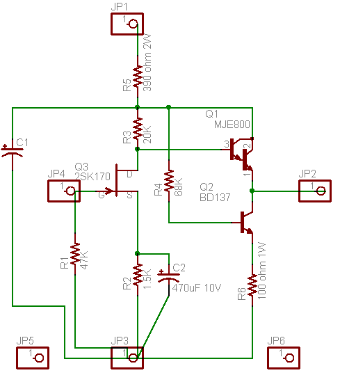
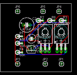
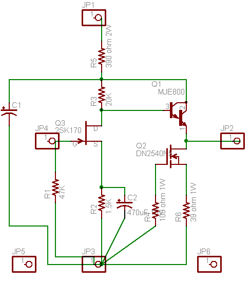
This first implementation was a Hamptone spinoff. Here is a rough idea of the PCB layout, I'm still learning EagleCad so I haven't got a few things figured out yet.

SSEGM1S.gif


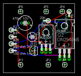
I may end up adding a reistor in series with the gate of the 2SK170, so the same layout can work for bipolars as well. I have adopted an offset in the layout to avoid plugging the module in the wrong way. See where I'm at below.

SSEGM1L.gif
 
Without commenting on the utility of all this, please do something about the output stage current source load. As drawn it will be hugely device dependent and vary with PS and temperature, etc.

There are plenty of more than adequate stabilized current sources published. Simple is good, as long as it isn't so simple that it isn't reliable or repeatable.

JR
 
The circuit the author proposes draws a lot of current, has limited input (+/-0.6V) and output swing(+/-5.0V). It functions more like a circuit built for a specific app, definietly not one suited for consideration of universal gain module. Better use can be made of the voltage rail than to feed a 390 ohm resistor.

analag
 
Let me join your brain-storm...

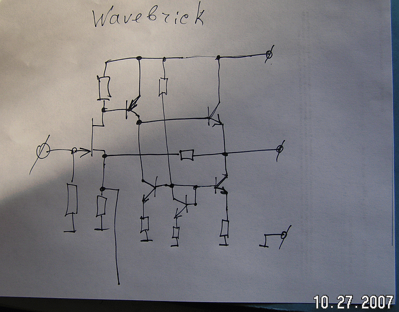
One more version: non-inverting, more gain, lower output resistance, higher input resistance, less audible distortions, large output swing. To increase gain use capacitor with resistor in series to the ground, to decrease gain use it to output, for unity gain just a capacitor to output. Like an "Audio OpAmp" with huge input resistance on non-inverting input and reasonable input resistance on inverting input. However, DC feedback will shift a working point, but it is for audio, not for instrumentations...

wavebrick.gif
 
Hey all,

Just saw this thread so I did a layout of the BA283AM & BA283NV using the proposed dimensions and pin out. I made a couple of part substitutions. The 2N3055 is a TO-220 part and the film caps are box types with 5mm pitch. Other than that the circuit is the same.

Here's the layout:
-283AM
-283NV

I have gerbers if anyone wants them.
ba283avDOA.zip
 
[quote author="analag"]The circuit the author proposes draws a lot of current, has limited input (+/-0.6V) and output swing(+/-5.0V). It functions more like a circuit built for a specific app, definietly not one suited for consideration of universal gain module. Better use can be made of the voltage rail than to feed a 390 ohm resistor.

analag[/quote]

The FET can only handle 40V so the 390 ohm resistor drops about 9V, I don't get how you are getting to +/-5V swing.
 
[quote author="Wavebourn"]Let me join your brain-storm...

One more version: non-inverting, more gain, lower output resistance, higher input resistance, less audible distortions, large output swing. To increase gain use capacitor with resistor in series to the ground, to decrease gain use it to output, for unity gain just a capacitor to output. Like an "Audio OpAmp" with huge input resistance on non-inverting input and reasonable input resistance on inverting input. However, DC feedback will shift a working point, but it is for audio, not for instrumentations...

http://wavebourn.com/images/wavebrick.gif[/quote]
That's a nice one, would be a nice update for making this circuit below more universal. I like it.

http://electronicdave.myhosting.net/miscimages/1588B-3.gif

As I thought to have seen though, the Altec has just the right
adaptation to 200 Ohm mics (w.r.t. noise; or to 2k sources when skipping the TX), so making circuits more 'universal' can be a compomise. In other words the FET-version my not be optimal for all applications, but could be adapted for of course with some redimensioning.

Regards,

Peter
 
[quote author="clintrubber"][quote author="Wavebourn"]Let me join your brain-storm...

One more version: non-inverting, more gain, lower output resistance, higher input resistance, less audible distortions, large output swing. To increase gain use capacitor with resistor in series to the ground, to decrease gain use it to output, for unity gain just a capacitor to output. Like an "Audio OpAmp" with huge input resistance on non-inverting input and reasonable input resistance on inverting input. However, DC feedback will shift a working point, but it is for audio, not for instrumentations...

http://wavebourn.com/images/wavebrick.gif[/quote]
That's a nice one, would be a nice update for making this circuit below more universal. I like it.

http://electronicdave.myhosting.net/miscimages/1588B-3.gif

As I thought to have seen though, the Altec has just the right
adaptation to 200 Ohm mics (w.r.t. noise; or to 2k sources when skipping the TX), so making circuits more 'universal' can be a compomise. In other words the FET-version my not be optimal for all applications, but could be adapted for of course with some redimensioning.


[/quote]

Peter;

I always knew that Altec engineers were smart guys. I started to respect them more when suddenly found schematics of their vintage 1569 amp that looks like a sister of mine. :thumb: Indeed, the same cat may be skinned by multiple ways, but very few of them will be optimal.
 
[quote author="AMZ-FX"]IMHO, the modules should be more generic:

SSEGM3a.gif


Let it run open loop by leaving pin2 open, OR increase gain by putting a large capacitor from pin2 to ground, OR connect a resistor from pin2 to pin1 to provide feedback to limit gain to a set value.[/quote]

The discussion seems to have moved past this design, but I'd like to look back at it for one reason: unless I've gotten my ups and downs confused, running feedback from the output to pin 2 would create positive feedback and either higher distortion or, probably, a nice oscillator.

Peace,
Paul
 
In one of the old threads the "book standard" Add two diodes to ground adjust the 68K resistor and adjust the bottom emitter resistor for the desired current was brought up
One diode and the BE drop fall out for 1 diode drop divided by the resistor as the constant current: However PRR? or someone else posted something like maybe the circuit drawn as shown "sounded better" I am to lazy to look for the thread.

I don't like the design because it looks like the output stage would be very temp depended MAYBE it works because it is in a box and kind of is in a temp oven when it is warmed up.

Looks like one needs a certain hfe vs current vs temp range for the bottom BJT
 
gentlemen;

let's switch to my schemo since it is more adequate?

However, if someone already patented such combination of transistors, resistors, capacitors... we may say him "thank you and go away from DIY community"
 
There are many book standard current sources but any one of several will work adequately well.

The only way the IMO too simple current source could sound better is if there is some interaction with a compliance in the PS load dynamically changing that load current, or if the static current is not similar and adequate. Since small modulations on that current will be a secondary effect I am more suspicious of the nominal current. Of course without overall negative feedback it all has some impact.

JR
 
[quote author="JohnRoberts"]The only way the IMO too simple current source could sound better is if there is some interaction with a compliance in the PS load dynamically changing that load current, or if the static current is not similar and adequate. Since small modulations on that current will be a secondary effect I am more suspicious of the nominal current. Of course without overall negative feedback it all has some impact.

JR[/quote]

It's very messy. There are also signal-induced thermal distortions that will interact at low frequencies. The circuit is a good example of parts count minimization taken too far IMO...but if you are only making a few of them and have the patience to tweak, I hope you enjoy the ride. My advice: don't quit the day gig.
 
Back
Top