MK7 - tube mic project

GroupDIY Audio Forum

Help Support GroupDIY Audio Forum:

This site may earn a commission from merchant affiliate links, including eBay, Amazon, and others.
loopermc5 said:
Hello all so my heater voltage is fine with no tube as soon as I plug in the tube poof it's gone I have tested the tubes they are fine checked and rechecked the psu and mic pcb what could be the causes for this? it's all so simple and yet i can figure it out any hints would be great as my head hurts at this point.

thanks?
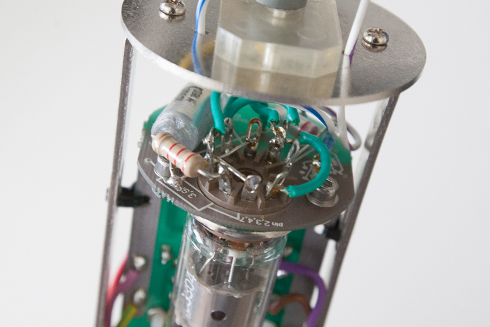
I had problems with tube socket that couldn't fit through the hole in pcb. The tube socket solder lugs went through but slightly touched edge of the hole. Te ground pour around the hole then made slight touch with some of the lugs generating weird problems like yours.

Just sleep your headache over and try again. Im sure it is something simple;)

Ps. Please use . on your posts.
 
Hi Guys,

So I'm finally getting around to building my MK7, that I bought back in 2008...

I'm using Moby's PSU board and have built it all up, I'm getting 140V on my B+ (Schematic shows 150V), unloaded the Heater is 8.1V (Schematic is 7.6VDC for an EF86, which I'm using). Pattern voltages are 0V, 53V, 107V (Schematic shows 0V, 60V, 120V).

All the connections look solid and ohm out from the PSU through the cable to the mic itself, but, it's not working  :-[

The moment I add the EF86 the Heater voltage drops from the 8.1V to 4.2V, I've tried it with a few EF86 tubes and it does the same thing each time.

I chose to wire it self-biased as per the general consensus in this thread.

The power trafo was custom wound for me and even under load I'm still getting 11.7VAC on the 12V Sec and 152.3VAC on the HT Sec.

Any thoughts?

Also RE the capsule, I'm using one of Dale's original M7's, on the backplate, around the circumference is a bluish tape, should that be removed? Likewise when tightening it into the capsule holder, do I need to pierce the  blue tape with the screws, i.e bind down onto the steel, or make an effort NOT to touch it, i.e does the film act and an insulator?

Any help would be MUCH appreciated!

Cheers

Matt


matta said:
Also RE the capsule, I'm using one of Dale's original M7's, on the backplate, around the circumference is a bluish tape, should that be removed? Likewise when tightening it into the capsule holder, do I need to pierce the  blue tape with the screws, i.e bind down onto the steel, or make an effort NOT to touch it, i.e does the film act and an insulator?

NOOOOOOO don't remove the tape nor pierce it!

Self bias is easier on the PSU noise requirements, but it's not "better". I'd say fixed bias is more like the original.
So i'm not sure which schematic exactly is used for the psu & heater string - maybe you could elaborate?

-max

 
Hi Max,

Thanks for the heads up with the capsule, so at least I have that right!

RE the heater issue, solved that, I had the PSU pilot light running in parallel, which caused the voltage drop  :-[

So now my heaters are looking good, even when loaded and I can see them glowing, a little. Still no sound though  :-\

I'm using your passive PSU design, with the triad choke, built using Moby's board.

As shared the rest of the voltages look ok, as listed above. Ohmed out the connection from PSU through to mic, all look good there as well. Tried a few EF tubes, no difference, other than the heater voltages changed a bit between manufactures.

Thoughts?

Thanks in advance!

Matt


ioaudio said:
matta said:
Also RE the capsule, I'm using one of Dale's original M7's, on the backplate, around the circumference is a bluish tape, should that be removed? Likewise when tightening it into the capsule holder, do I need to pierce the  blue tape with the screws, i.e bind down onto the steel, or make an effort NOT to touch it, i.e does the film act and an insulator?

NOOOOOOO don't remove the tape nor pierce it!

Self bias is easier on the PSU noise requirements, but it's not "better". I'd say fixed bias is more like the original.
So i'm not sure which schematic exactly is used for the psu & heater string - maybe you could elaborate?

-max
 
Matta,

i assume you measure 5,7 volts across pin 5 and 4 of the tube?
Usually the glow of a ef86 is very weak.
Other than that re-check all connections, grounding etc.
 
Hi Max,

Yes, it's looking good there. 5,8V across Pin 5 and 4 and 1.81V on the junction between Pin7,2,3 and the 2K2 resistor.

I've checked all the connections, triple checked them. Could the capsule or transformer be damaged in any way? I should be hearing SOMETHING right? There isn't any hum, it's clean, just no audio. Even cycling through the patterns doesn't do a thing, no pops/clicks. Though if I touch my meter to the 100M resistors that connect to the back plate and rear capsule I can hear it, like a little zap, so audio must be getting through the XLR to the mic pre?

On paper it all seems ok  :-[

Thanks

Matt

ioaudio said:
Matta,

i assume you measure 5,7 volts across pin 5 and 4 of the tube?
Usually the glow of a ef86 is very weak.
Other than that re-check all connections, grounding etc.
 
I'm trying to remember things from 5 years ago - probably the grounding connections at the tube sockets - what is your voltage at the anode, pin6?

 
Hey Max,

Yeah, thought it may be the grounding, but I ohmed it out and all seems good there. I've actually just reflowed all the solder joints incase there was a cold one, but to no avail. I'm getting 67V on the anode, pin 6, if that helps!

As per the schematic I've got 59V of the 60V's shown at the junction of 1M4, 100M and 1M2 resistors.

I appreciate the help, I know that it's jogging your memory a bit! Know that it is appreciated.

Here are a few pics of the mic. The additional pink and yellow/green wires ground the output transformer and mic body accordingly.

MK7-1.jpg


MK7-2.jpg


MK7-3.jpg


Cheers

Matt

ioaudio said:
I'm trying to remember things from 5 years ago - probably the grounding connections at the tube sockets - what is your voltage at the anode, pin6?
 
@ matta, I  noticed the pcb is not grounded to the rail at the mounting holes...I just got mine about finished and had trouble from such a simple oversight.
 
matt,

check that the tube socket has continuity to ground. the metal part!


or maybe bad coupling cap like skylar suggests on page 35...


and this, max's post about the self biasing:

"for self bias the gold/super caps can be ommited, for a ef86 additionally the 2,2R and the 3,9 resistor should be left out"
 
i got quite a low heater voltage on my MK7 build i just finished .
can the first 4,7 Ω resistor of the passive PS be left away ?
this way i get to the required voltages .

also i got some hum . before reading through all 40 pages , can someone give me some tips on reducing the hum ?
 
yeah do away with 4.7 or parallel small values with resistors in crc filter.
hum is probably due to grounding/shielding
 
My understanding is that in general if the hum is 100/120hz then it's a PSU issue (like insufficient filtering) and if it's 50/60hz then it's a grounding issue.

ie; full-wave rectification creates 100/120hz humpy-doo's.

Cheers,
jb
 
nashkato said:
also i got some hum . before reading through all 40 pages , can someone give me some tips on reducing the hum ?

I went through my documentation vault and found out it was the user "Emperor Tomato Ketchup" who posted a great grounding setup for MK7. I got lazy when I built mine and simply followed that one. Perfect noise floor from the start.

The thread is here: www.groupdiy.com/index.php?topic=36857

But it seems the image is lost to the mists of time so I've included a copy on the bottom of this post.

If it's a PSU filtering issue you should try to measure it as accurately as possible and post the data here. Then we can help you further. If it's the passive PSU from the group buy that I organized long a go, it should deliver perfect heater and B+. Removing the first 4R7 CRC resistor should be an ok solution if your PSU transformer doesn't quite deliver high enough VAC for the load. The original is a bit overkill even for a passive filtering set up (but better safe than sorry).

If it's none of the above there's a chance your mic body head basket grill is inadequate for shielding (what mic body, how many grill layers etc.). Or maybe you have a simple soldering glitch or build error somewhere.
 

Attachments

  • MK7-grounding.jpg
    MK7-grounding.jpg
    73.7 KB · Views: 103
Ha! Now I am remembering... That's what worked on mine too but shouldn't the body/head-basket be connected to shield/chassis for safety? Which should also work if the PCB is floating with it's own gnd-path on pin-7 instead of making sure to connect PCB-GND to body.

I also had hum with the body connected to shield/chassis so I had to float that shield/body connection on the mic-side of the cable to get rid of it.

I originally installed PF86's in the mk7's but have recently acquired some EF86's and EF800's that I want to try in there so when I open them up I'm planning to test out my theory with the grounding in any case because I feel it's a safety issue with HT / B+ in there and don't want to bite the talent under any circumstance.

Cheers,
jonathan
 
0dbfs said:
That's what worked on mine too but shouldn't the body/head-basket be connected to shield/chassis for safety?

Now that you mention it, I have a vague memory I actually did that with the cable shield. You paid for all 7 pins, use them on the mic end as well!

(just make sure you have complete isolation of mic body shield ground, and the mic circuit internal ground. these two touching inside the mic is a ground loop)

But the difference in safety is negligible, and in performance none. Heater voltage is so low you can't even feel when touching it directly and B+ current is tiny and voltage somewhat low as well.

[edit]

just checked my build documentation, and no I didn't actually go through with this. I dropped the idea because of the difficulty isolating mic body and internal ground. Also, the fact mic body chassis was only several (fat) wires away from PSU chassis (and IEC) physically. Trust those screw terminal blocks!
 
just measured the hum .
it´s a 50 Hz with app. 100mVpp.
i´ll go through your suggestions starting with Emporer Tomato Ketchup´s grounding scheme .
thanks all i´ll keep you posted.

ps : in the meanwhile i threw out the Choke and did the LM317 regulated Heater supply . it got a little better , but far from being good enough.
 
nashkato said:
just measured the hum .
it´s a 50 Hz with app. 100mVpp.
i´ll go through your suggestions starting with Emporer Tomato Ketchup´s grounding scheme .
thanks all i´ll keep you posted.

ps : in the meanwhile i threw out the Choke and did the LM317 regulated Heater supply . it got a little better , but far from being good enough.

It sounds like the shield isn't working properly. Check for conituity between all outer metal parts. Also make sure you put the mic back together before testing audio quality, or that hum will be the result.

-James-
 
Back
Top