EEMO1 said:
matt,
check that the tube socket has continuity to ground. the metal part!
or maybe bad coupling cap like skylar suggests on page 35...
and this, max's post about the self biasing:
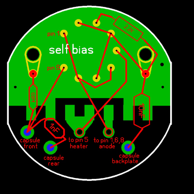
"for self bias the gold/super caps can be ommited, for a ef86 additionally the 2,2R and the 3,9 resistor should be left out"
Hi EEM01,
Like you mentioned in one of your previous posts, this project has kicked me in the nuts! I've started to doubt my own abilities, and so like you I put it on the shelf and finally have some time to pick it up again.
Thanks for your suggestions, I've checked the grounding on the tube socket, it's all good, ohms out perfectly!
I'll look into the bad output caps as a last resort, firstly want to clear this up.
"for self bias the gold/super caps can be ommited, for a ef86 additionally the 2,2R and the 3,9 resistor should be left out"
I'm using and EF86, self-biased, can't seem to find where Max suggested leaving those resistors out.
EDIT: Ok, I just found it:
as already noted, a different approach changes the bias method , adding a cathode resistor for self bias and disconnecting the heater rail completely from the audio path - this is the easy way and works with the unmodded stock psu, except for the pattern switch assembly. for self bias the gold/super caps can be ommited, for a ef86 additionally the 2,2R and the 3,9 resistor should be left out.
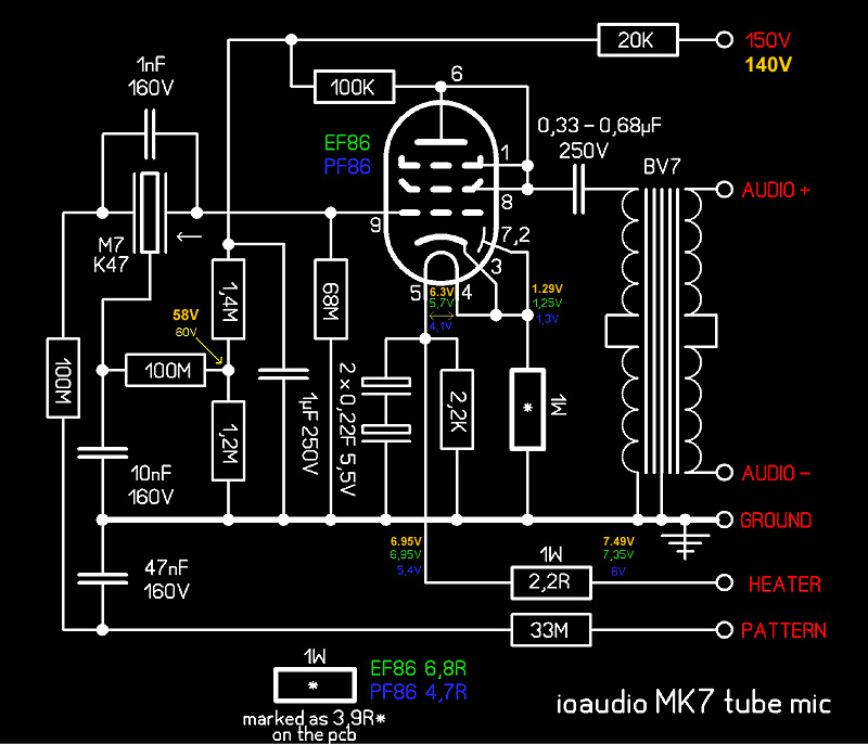
For my self-bias of the EF86 I'm using the diagram in the first post, replacing the 3R9 resistor as screened with the 2K2, I assume that's the 3R9 Max is talking about?
RE the 2R2, mine is fitted! Am I correct in thinking it should be removed and jumpered? Is that what you've done with your own mic? I also have the 2 x gold super caps fitted as well? Just looking for some clarification?
Really hoping to get to the bottom of this all not that I've taken some time away from it.
I spotted this in an earlier comment from Max.
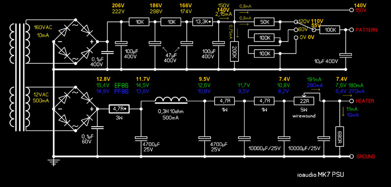
for tubes with a 6,3v heater (ef86 etc) , the psu has to be modded to supply ~9vcd and two resistors (2,2R* & 3,9R*) have to be
I'm using an EF86 and haven't changed anything on the power supply, I built it as spec, is this the issue, were those changes and resistors documented for those who used EF86 tubes?
@shabtek, the rails are grounded to the PCB via wire from the PCB ground plane to the rails via a soldered wire and lug.
Thanks in advance!
Matt