You are using an out of date browser. It may not display this or other websites correctly.
You should upgrade or use an alternative browser.
You should upgrade or use an alternative browser.
Neumann U 47 Clone - A DIY Bachelor Thesis
- Thread starter Zottel
- Start date


Help Support GroupDIY Audio Forum:
This site may earn a commission from merchant affiliate
links, including eBay, Amazon, and others.
Pip
Well-known member
Zottel said:Thanks again folks!
Ok Pip Thanks a million! To you still thinkthis might need some kind of rubber to protect the tube from shocks?
Andrew i send you a email")
Yes I think if you use any kind of can tube you should shock mount it. Mr. Grosser's VF14ef that is for him to answer as it is not a tube but a FET solution that fits into a U47 unaltered. As I understand it he will sell it if he installs it.
From his website:
Da Original Telefunken VF14 Röhren als Ersatzteil nicht in ausreichender Menge oder Qualität zur Verfügung stehen, hat A. Grosser eine FET Schaltung in einem Röhrengehäuse als Austauschtyp entwickelt. Diese Schaltung entspricht in ihrem Verzerrungsverhalten und anderen wichtigen Parametern exakt der VF14. Somit können Neumann U47 Mikrofone auf unbestimmte Zeit weiter betrieben werden. Die VF14ef wird nicht lose verkauft, sondern - falls erforderlich oder ausdrücklich verlangt- bei Reparaturen und Mikrofonprüfungen durch A. Grosser eingesetzt. Der Einsatz der VF14ef erfordert keinerlei Umbauten oder Modifikationen an Mikrofon oder Netzteil. Die VF14ef wird standardmässig von vielen bekannten Produzenten und Studiobetreibern eingesetzt, um die wertvolle Originalröhre zu schonen. Klanglich ist kein Unterschied festzustellen.
English: (please excuse the bad translation)
Since original Telefunken not stand VF14 tubes as spare parts in sufficient quantity or quality of available A. Grosser has developed an FET circuit in a tubular housing as a replacement type . This circuit corresponds to their distortion behavior and other important parameters exactly the VF14 . Thus, Neumann U47 microphones are on indefinitely . The VF14ef is not sold loose but - used if required or expressly verlangt- repairs and microphone tests by A. Grosser . The use of VF14ef requires no conversions or modifications to the microphone or power supply . The VF14ef defaults used by many well-known producers and studio owners to protect the valuable original tube . Sonically there is no difference noted
Thanks for the reply!
Cool, i was thinking the same about Grossers VF14EF.
Sorry for all these questions...This is my first DIY project :-[
Its hard to source the high omic resistors!
60 MOhm with 0,5 Watt is impossible to find!
For 100 MOhm ill take this one:
http://de.rs-online.com/web/p/widerstande-durchsteckmontage/8492707/ ???
How much difference in the tollerance do you guys accept for your builds?
Lets sey a 0,47 uF instead of a 0,5 uF?
I wouldn't worry about the 60MΩ. If you're buying from RS, replace it with a 100MΩ instead (R1 & R2 both 100MΩ).
Technically you can increase R2 to anywhere upto 1GΩ for different results. Everyone has a personal preference, mine is around 200MΩ.
For your capacitors, with manufacturing tolerances as high as 20%, 0.47 is more than fine.
Technically you can increase R2 to anywhere upto 1GΩ for different results. Everyone has a personal preference, mine is around 200MΩ.
For your capacitors, with manufacturing tolerances as high as 20%, 0.47 is more than fine.
Zottel said:Its hard to source the high omic resistors!
60 MOhm with 0,5 Watt is impossible to find!
For 100 MOhm ill take this one:
http://de.rs-online.com/web/p/widerstande-durchsteckmontage/8492707/ ???
There is another option for the EF-14 tube. Saturn Sound says they have the missing link that is suppose to be as close to the real tube as you can get. Also they have the 1780ohm wire wound resistor that is very are to find. I have been doing a lot of research because I have been very interested in building an original u47 clone myself. Very hard to find reasonable priced parts though.
Here is the website to contact these guys if you would like.
http://www.saturn-sound.com/products/replacement%20valve.htm
Here is the website to contact these guys if you would like.
http://www.saturn-sound.com/products/replacement%20valve.htm
And what exactly is so "magical" or "esoteric" about a resistor that's used to derive the filament supply voltage? And wouldn't the (more) standard 1.8kohm value be close enough (1,1% off)?
http://fi.farnell.com/webapp/wcs/stores/servlet/Search?catalogId=15001&langId=358&storeId=10159&categoryId=700000005447&sort=P_PRICE&pageSize=25&showResults=true&pf=110005202,110005236,110124826
And for what it's worth, when looking up a schematic for the U47, i came across this: http://www.tab-funkenwerk.com/id68.html
And wouldn't the (more) standard 1.8kohm value be close enough (1,1% off)?http://fi.farnell.com/webapp/wcs/stores/servlet/Search?catalogId=15001&langId=358&storeId=10159&categoryId=700000005447&sort=P_PRICE&pageSize=25&showResults=true&pf=110005202,110005236,110124826
And for what it's worth, when looking up a schematic for the U47, i came across this: http://www.tab-funkenwerk.com/id68.html
Pip
Well-known member
Arkenberg said:There is another option for the EF-14 tube. Saturn Sound says they have the missing link that is suppose to be as close to the real tube as you can get. Also they have the 1780ohm wire wound resistor that is very are to find. I have been doing a lot of research because I have been very interested in building an original u47 clone myself. Very hard to find reasonable priced parts though.
Here is the website to contact these guys if you would like.
http://www.saturn-sound.com/products/replacement%20valve.htm
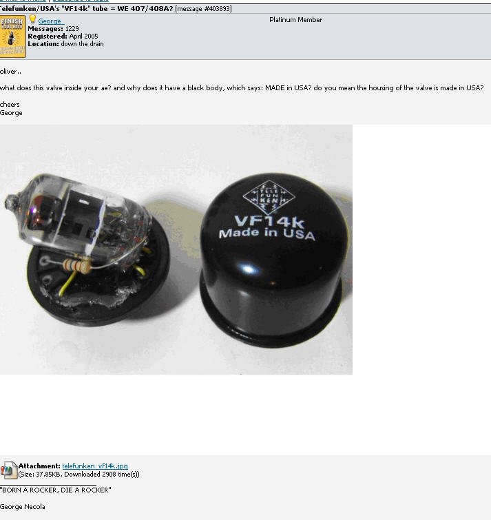
It is a 407a I am sure. The wirewound resistor is interesting as it does potentially allow for greater heat dissipation as that thing gets hot!
Also a 407a:
http://store.t-funk.com/p/vf14k-vacuum-tube-u47-u48?pp=24
http://www.westernelectric.com/spec_sheets/407A.pdf
JessJackson
Well-known member
I would read about people just throwing 407a tubes inside housing before buying a vf14k
Jess
http://repforums.prosoundweb.com/index.php?topic=28765.0
Jess
http://repforums.prosoundweb.com/index.php?topic=28765.0
Hey,
just wanted to let you know if you'r talking about the U47 schematic you should be aware that there have been many diffrent versions. These Versions can be groupt into three groups.
1.The first years
2.The main production
3.The last production years
For exapmle:
In the first years they used two 100 M Ohm resistor. In the main produktion they changed to one 100 M Ohm Resistor and one 60 MOhm Resistor.
While the mics from the first years go down to 30 Hz and are linear till 100 Hz,
the U47 from group 2. and 3. go down to 40 Hz and the linearity stops higher.
Phrazemaster
Well-known member
Yes! Doesn't hurt! Plus then you know you've got the right part.Zottel said:Hey ho! I'm thinking about one thing:
Lets say you need one 100 Ohm resistor. But you've got 10 of them flying around. So do you measure them out and take the closest one?
I measure every component prior to installation, except maybe tiny capacitors.
Thanks for the reply! Sadly i only got two 100MOhm resistors and both of them ar 101MOhm. Does this have an effect?
For the next question i have to quote someone from this forum but I've forgotten who's written this:
"The high impedance is point to point on a plexiglas (or equivalent), you can improve it with Teflon pins "
Teflon Pins... For example this one:
http://www.mouser.de/ProductDetail/Keystone-Electronics/11075/?qs=%2fha2pyFadujd854sjBaBMRFiF94OUuVOHA7FT29xN3U%3d
http://www.mouser.de/ProductDetail/Keystone-Electronics/11511/?qs=sGAEpiMZZMtzcnMBgC2bs1gRn%252bbiduJ072z49Pederc%3d
How do you attach these things to the plexiglas? If i look at the datasheet ther's no screw! No female screw.. Nothing?!
Maybe you guys could help me out one more time ?
I will need something similiar to get the connection from the capsule part of the mic to the high omic part.
http://www.amazon.com/EMC-33-Threaded-Feed-Thru-Terminals/dp/B00KTEFC1O
+ Looking for a german/european dealer so i dont have to spent the 20 bucks for shipping.
Sadly i only got two 100MOhm resistors and both of them ar 101MOhm. Does this have an effect?For the next question i have to quote someone from this forum but I've forgotten who's written this:
"The high impedance is point to point on a plexiglas (or equivalent), you can improve it with Teflon pins "
Teflon Pins... For example this one:
http://www.mouser.de/ProductDetail/Keystone-Electronics/11075/?qs=%2fha2pyFadujd854sjBaBMRFiF94OUuVOHA7FT29xN3U%3d
http://www.mouser.de/ProductDetail/Keystone-Electronics/11511/?qs=sGAEpiMZZMtzcnMBgC2bs1gRn%252bbiduJ072z49Pederc%3d
How do you attach these things to the plexiglas? If i look at the datasheet ther's no screw! No female screw.. Nothing?!
Maybe you guys could help me out one more time ?
I will need something similiar to get the connection from the capsule part of the mic to the high omic part.
http://www.amazon.com/EMC-33-Threaded-Feed-Thru-Terminals/dp/B00KTEFC1O
+ Looking for a german/european dealer so i dont have to spent the 20 bucks for shipping.
Phrazemaster
Well-known member
Hi Zottel, 101mOhm is fine. Sometimes people replace these kinds of resistors with much higher values. No worries mate!
Wish I could help you on the second issue; maybe someone else can chime in here...
Best,
Mike
Wish I could help you on the second issue; maybe someone else can chime in here...
Best,
Mike
Majestic12
Well-known member
The teflon pins are press-fit. You need to drill a hole that matches the specifications in the datasheet and than press the pin into the hole. It will hold simply by friction when you are doing it right.
Allright thanks!
Next question would be about the 1780 Ohm Resistor as I found out 2 days ago Neumann build these things themself. It looked like this:

If I'd build this thing on my own is the following way okay?:
As base i have cut a the inner cardbox of a role of duct tape. Fits good!
As wire i would use this: http://www.spulen.com/widerstandsdraht-0-032mm-1650-ohm-meter-klasse-bis-1ppm-k.html
As I reckon in the worst case 1510 Ohm =1000mm
so 1 Ohm = 0,66 mm
1780 Ohm = 1178 mm
the cadbox has an hight of 13 mm and a lenght of 65 mm. -8 mm for the connection = 57 mm.
as the wire is wound around this carbox i got ~ 26 mm for one winding.
1178mm/26mm =45 windings
So there would be 8 windings per 10 mm.
Sounds good? I dont know if the wire is to thin for the 5 Watt ? Its 0,032 mm thick.
To isolate the cardboy and the housing of the mic, and also for the aluminium plate that holds this resistor in place, Id use this: http://www.shop.hightechflon.com/ptfe-teflon-tape-selfadhesive/Page-16-2-96-32.aspx
What do you think about it?
Next question would be about the 1780 Ohm Resistor as I found out 2 days ago Neumann build these things themself. It looked like this:
If I'd build this thing on my own is the following way okay?:
As base i have cut a the inner cardbox of a role of duct tape. Fits good!
As wire i would use this: http://www.spulen.com/widerstandsdraht-0-032mm-1650-ohm-meter-klasse-bis-1ppm-k.html
As I reckon in the worst case 1510 Ohm =1000mm
so 1 Ohm = 0,66 mm
1780 Ohm = 1178 mm
the cadbox has an hight of 13 mm and a lenght of 65 mm. -8 mm for the connection = 57 mm.
as the wire is wound around this carbox i got ~ 26 mm for one winding.
1178mm/26mm =45 windings
So there would be 8 windings per 10 mm.
Sounds good? I dont know if the wire is to thin for the 5 Watt ? Its 0,032 mm thick.
To isolate the cardboy and the housing of the mic, and also for the aluminium plate that holds this resistor in place, Id use this: http://www.shop.hightechflon.com/ptfe-teflon-tape-selfadhesive/Page-16-2-96-32.aspx
What do you think about it?
If your interested in the creation of the wirewound resistor check this thread:
http://groupdiy.com/index.php?topic=61528.msg782111#msg782111
http://groupdiy.com/index.php?topic=61528.msg782111#msg782111
Zottel said:Allright thanks!
Next question would be about the 1780 Ohm Resistor as I found out 2 days ago Neumann build these things themself. It looked like this:
If I'd build this thing on my own is the following way okay?:
As base i have cut a the inner cardbox of a role of duct tape. Fits good!
As wire i would use this: http://www.spulen.com/widerstandsdraht-0-032mm-1650-ohm-meter-klasse-bis-1ppm-k.html
As I reckon in the worst case 1510 Ohm =1000mm
so 1 Ohm = 0,66 mm
1780 Ohm = 1178 mm
the cadbox has an hight of 13 mm and a lenght of 65 mm. -8 mm for the connection = 57 mm.
as the wire is wound around this carbox i got ~ 26 mm for one winding.
1178mm/26mm =45 windings
So there would be 8 windings per 10 mm.
Sounds good? I dont know if the wire is to thin for the 5 Watt ? Its 0,032 mm thick.
To isolate the cardboy and the housing of the mic, and also for the aluminium plate that holds this resistor in place, Id use this: http://www.shop.hightechflon.com/ptfe-teflon-tape-selfadhesive/Page-16-2-96-32.aspx
What do you think about it?
As I mentioned before Saturn sound is making these 1780ohm resistors. So you might have call them.
http://www.saturn-sound.com/products/replacement%20valve.htm

Similar threads
- Replies
- 25
- Views
- 2K
- Replies
- 67
- Views
- 3K
- Replies
- 108
- Views
- 11K
- Replies
- 5
- Views
- 619
Latest posts
-

-

-
-

-

-
 Built custom channel for Soundcraft Boards (SSL like)
- Latest: MidnightArrakis
-

-