Neumann Vintage U87 Clone : Build Thread.

GroupDIY Audio Forum

Help Support GroupDIY Audio Forum:

This site may earn a commission from merchant affiliate links, including eBay, Amazon, and others.
Hello !
I don't arrive to FET the Bias :(
It is necessary that the microphone is connected in 48v ?
I have a species of signal mid-square, mid-sine.
I however followed the tutorial of Matador.
Who has a other tutorial?
Thanks !
 
here is how to install the peluso capsule ,

58d0281993cba.12.10.jpg


Hope this helps,

Dan
 
yankimusic said:
Hello !
I don't arrive to FET the Bias :(
It is necessary that the microphone is connected in 48v ?
I have a species of signal mid-square, mid-sine.
I however followed the tutorial of Matador.
Who has a other tutorial?
Thanks !

Yes it is necessary to operate the mic with the 48V , Are you measuring the drain of the FET  ,,  set a Voltage of 11.5V on the Drain and test the mic to see what happen  ,and then come back to bias,
Where do you inject the bias signal,
Dany,

 
poctop said:
here is how to install the peluso capsule ,

2013-04-05%2019.12.10.jpg


Hope this helps,

Dan

Are you sure this picture is labeled correctly? The initial image you posted for capsule connections has the diaphragms reversed. Just checking to make sure I don't need to re-wire my mic...

-James-
 
So, if I screw the rbk lead in, and the screw bottoms out, will this ground the two outer rings together? The front and back edges aren't isolated on my capsule, and I'm curious to know if this is the reason. I had a screw that was a hair too long, and it bottomed out and the head of the screw twisted off. If this is the case, it looks like my u87 will be cardioid only, which I don't mind too much, because it sounds excellent either way. If anyone knows the inside of these capsule, can you please help me verify this?

Thanks,
Chad
 
HellfireStudios said:
poctop said:
here is how to install the peluso capsule ,

58d0281993cce.12.10.jpg


Hope this helps,

Dan

Are you sure this picture is labeled correctly? The initial image you posted for capsule connections has the diaphragms reversed. Just checking to make sure I don't need to re-wire my mic...

-James-

Usually as per the orginal capsule ,  the opposite backplate connection represent the front of the capsule ,  but if both side are matched correctly wich should be with a quality capsule it does not matter,  if you have any doubt then you can try both side and if you find that the cardiod sounds best on one side you can select the side the more pleasing to you but in theory there it should be that way ,

Best,
DAny
 
Volume11 said:
So, if I screw the rbk lead in, and the screw bottoms out, will this ground the two outer rings together? The front and back edges aren't isolated on my capsule, and I'm curious to know if this is the reason. I had a screw that was a hair too long, and it bottomed out and the head of the screw twisted off. If this is the case, it looks like my u87 will be cardioid only, which I don't mind too much, because it sounds excellent either way. If anyone knows the inside of these capsule, can you please help me verify this?

Thanks,
Chad

The proper capsule will have its backplates isolated by a very thin plastic spacer between them. The screws in the sides of the capsule should have no affect on its isolation. Which capsule are you using?

-James-
 
I am using a beesneez k8. The two center screws are isolated from one another, but the sides are not. When I remove the two side screws, I get continuity between the two outer edges (rbk and fbk, where the mount screws go). Is this what you are referring to? Thanks for the help.
 
Volume11 said:
I am using a beesneez k8. The two center screws are isolated from one another, but the sides are not. When I remove the two side screws, I get continuity between the two outer edges (rbk and fbk, where the mount screws go). Is this what you are referring to? Thanks for the help.

The capsule backplates should be isolated (no continuity). If they are not, you may have the wrong capsule type. In all fairness the only mic to use the isolated backplate version of the K-67 capsule is the vintage U-87. Unfortunately, the pattern selection of this project is dependent on the isolated backplates. Contact you capsule dealer, and get the correct capsule (if they make one).

-James-
 
poctop said:
yankimusic said:
Hello !
I don't arrive to FET the Bias :(
It is necessary that the microphone is connected in 48v ?
I have a species of signal mid-square, mid-sine.
I however followed the tutorial of Matador.
Who has a other tutorial?
Thanks !

Yes it is necessary to operate the mic with the 48V , Are you measuring the drain of the FET  ,,  set a Voltage of 11.5V on the Drain and test the mic to see what happen  ,and then come back to bias,
Where do you inject the bias signal,
Dany,

Thank you for your answer.
I did not make the test of the pile.
What can that bring to me?
I made you some photographs.
My signal is made with a cable mini jack, and starts from ableton live.
When I vary the potentionmeter, it does not occur anything the whole.
My oscillo is well in AC.

SDC11535.JPG

SDC11536.JPG

SDC11534.JPG
 
It seems tht you have 2 wire connected into the injection point ? ,  you need the "hot" part of the signal connected there only , and then the gnd of the signal to mic chassis ,

then the probe of the scope on the FET drain pin and then the probe gnd on the mic chasis as well,  i am not familliar with external computer setup but shold be the same pincple that applies,
hope this helps,

Dan,
 
poctop said:
It seems tht you have 2 wire connected into the injection point ? ,  you need the "hot" part of the signal connected there only , and then the gnd of the signal to mic chassis ,

then the probe of the scope on the FET drain pin and then the probe gnd on the mic chasis as well,  i am not familliar with external computer setup but shold be the same pincple that applies,
hope this helps,

Dan,

Thanks Dan.
I tested this method, and the problem persists.
I noticed something; I had been mistaken in XLR connection between the hot wire and the ground. I reversed connections, but the problem is always the same one.
Didn't I destroy my circuit with this inversion?
Should I perhaps reverse the potentiometer R11?
Thanks !
 
you should not have 2 wire connected on R6 for the bias ,  just take the measurement in DC voltage from the drain pin on the fet an set it to 11.5V and find out if the mic is cooperating 

Dan,
 
Thanks a lot !
I'll try.
After this, I can plug the transformer and capsule to test the microphone?
Not have to re-bias the FET? Always connected with the 48V?
 
yankimusic said:
Thanks a lot !
I'll try.
After this, I can plug the transformer and capsule to test the microphone?
Not have to re-bias the FET? Always connected with the 48V?

Yep,

DAny,
 
yankimusic said:
Thanks a lot !
I'll try.
After this, I can plug the transformer and capsule to test the microphone?
Not have to re-bias the FET? Always connected with the 48V?
Hello,

yes,you can attach both then.
The circuit doesn´t work without the 48v so yes you can apply phantom then.

About biasing with the scope method:

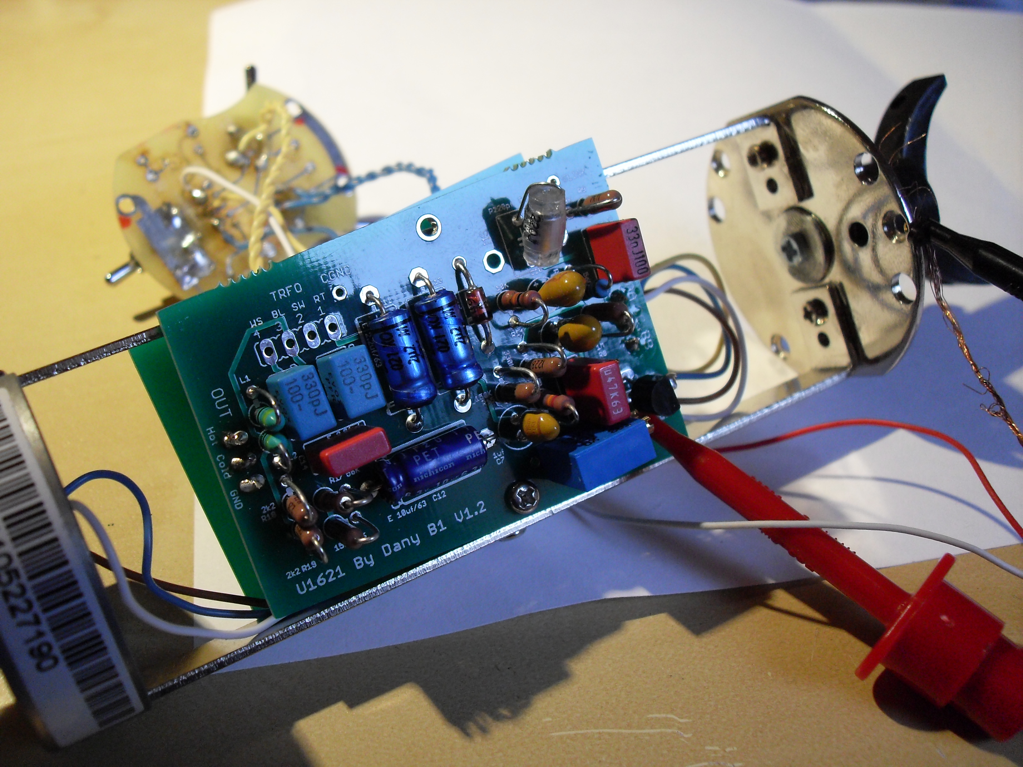
You can check your trim pot by connecting a dmm to the pot (set to Ohms) directly on the two solder pads (or pot legs if accessable).When you turn the trimmer the resistance onyour dmm must change,otherwise it might be broken or not connected correctly.
If this works out o.k. you can start again.

Dial the pot to max.resistance.
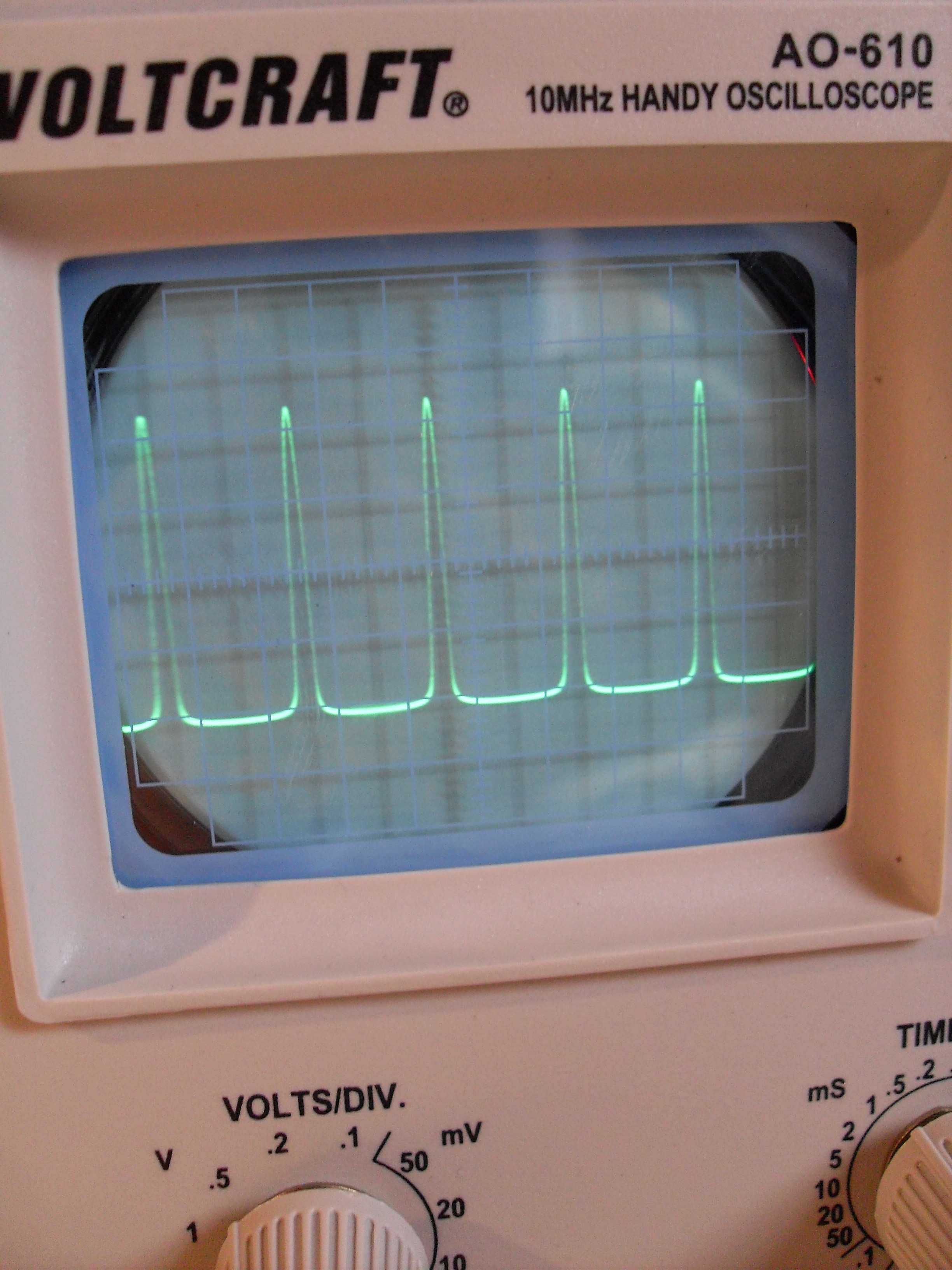
Apply the signal as before (your scope pic doesn´t look too bad,I hope you are apllying a real sine wave....it wouldn´t work with another non-symmetric waveform!).
You should bring down the send level a bit (from ableton or your audio-interface).
Your waveform already looks like a sine but only distorted on the lower part of it.
The goal is to make it flatten out on both top and bottom of it in an identical way.

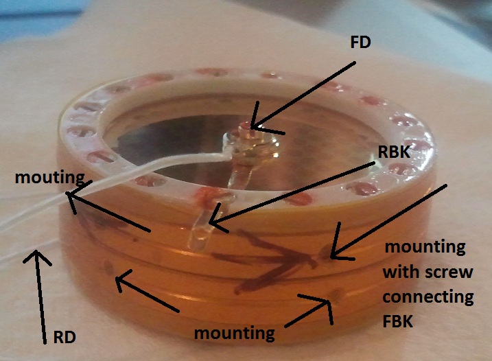
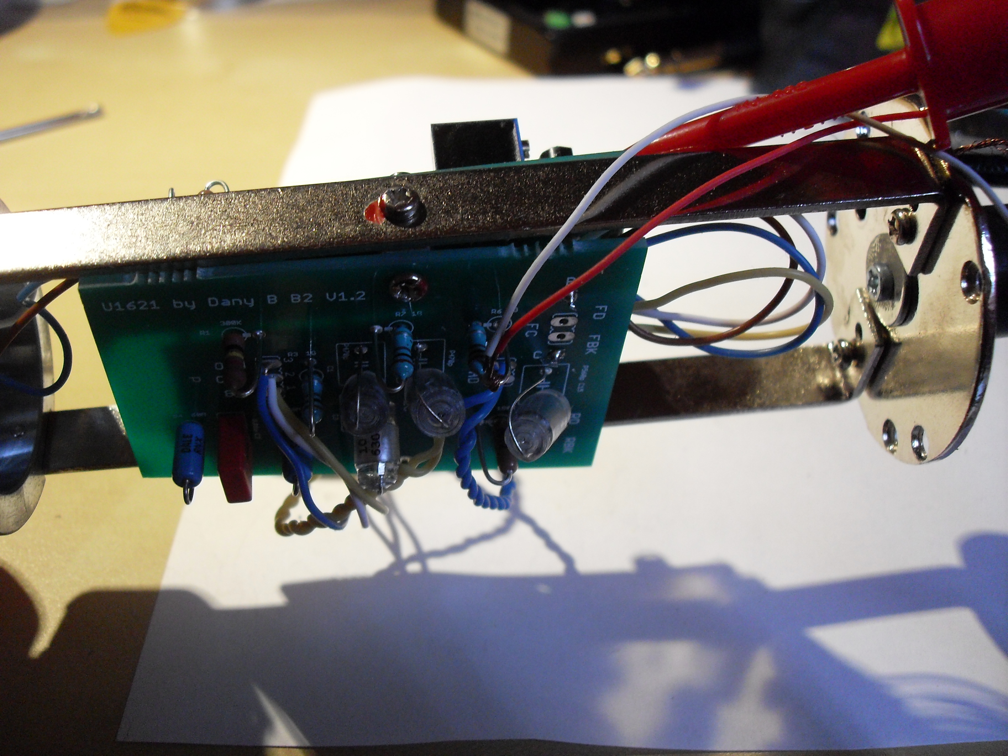
Btw.,I can not identify why there are two wires connected at R6,I hope it is just a mistake from your wiring?Curious because the scope seems to show something like 1 or more KiloHertz when I look at the Time(msec.)/Div. setting on the scope.

Anyway,it might be best to do like Dan said,bring it to 11,5vdc first.You can do scope biasing later on then.At least the waveform on your scope should have changed then saying the top should have started to flatten out too.

Hope to have helped,

Udo.
 
yankimusic said:
Thank you Udo and Dan ;) I connected my potentiometer such. Without cut and bend anything. Is this maybe the problem?
Don't know which board you are using.I did it with the early tapered types and had to cut off a pin and bend the others to make them fit the board.
Best to just measure the resistance at the solder pads (R11 if I remember correctly).Do one measure and then turn the pot screw some times,measure again and see if there is a change.

Best,

Udo.
 
poctop said:
you should not have 2 wire connected on R6 for the bias ,  just take the measurement in DC voltage from the drain pin on the fet an set it to 11.5V and find out if the mic is cooperating 

Dan,

I take the measurement between the FET and the body of the microphone?
 
kante1603 said:
yankimusic said:
Thank you Udo and Dan ;) I connected my potentiometer such. Without cut and bend anything. Is this maybe the problem?
Don't know which board you are using.I did it with the early tapered types and had to cut off a pin and bend the others to make them fit the board.
Best to just measure the resistance at the solder pads (R11 if I remember correctly).Do one measure and then turn the pot screw some times,measure again and see if there is a change.

Best,

Udo.

Thanks!
There is change between legs 1 and 2 and 2 and 3, but no change between legs 1 and 3.
 
Back
Top