Official 33609 builder's tread. See 1st page for updates.

GroupDIY Audio Forum

Help Support GroupDIY Audio Forum:

This site may earn a commission from merchant affiliate links, including eBay, Amazon, and others.
Lost notifications of this thread somehow, just turned on now.
BTW, some other thread notifications gone when forum changed interface to new. Or, I just have paranoja?
/As pure Addams: YES!!!!!!! :)
Promixe, can you make same measurements with my unit?
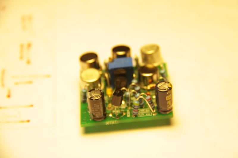
BTW, seems like timing capacitor (10uf) in "original" unit is about 1.4 times higher value than in "mine".
To get same time constants, just connect in parallel something about 3u3...4u7, 63V, I'd use WIMA poly.
 
Axelerator said:
Ok, its not to pricey also, will try them.
Hey Igor, you prefered a hi-b trunny for output, do you want to share specs ?
I am in contact with Sowter, they would make a trunny for me if i can give them more infos..
greets
axel

I used Hi-B C-cores from local factory, EILOR. They does not export.
The winding structure is same, thanx to CJ.

1:2.83 should work.

EDIT:
By mistake started to write about 2254C output trafo.  ;D
Have to go sleep, enough infernet for today))))


Hello,
Is it still possible to buy the 33609 pcb and any specialized components? I haven't been able to find it online. I'm definitely interested in finding a pcb, case, bom, etc.
thanks!
JS
 
Hi, I have the full 33609 PCB kit + a lot of components (caps, resistors, transistors, etc) for it. PM me if interested.

Thanks!

skidmorebay said:
Hello,
Is it still possible to buy the 33609 pcb and any specialized components? I haven't been able to find it online. I'm definitely interested in finding a pcb, case, bom, etc.
thanks!
JS
 
Hi there. I realize the last post here was a while ago, but I figured perhaps someone with a successful 33609 build might stumble upon it and share some insight!

I finally figured the power supply wiring and powered up my 33609. everything is fine until I connect the compressor board cable to channel 1 [cannel 2 is fine]. When this is connected, R26  [47R] starts to cook!I still can't find anything wrong. Does anyone have an idea of what I should be looking for? A particular short?

Note: I used BC237B transistors in place of the now-obsolete BC214 [only on the channel that I am having problems with, as I did not have enough BC214's!]. Could this be related?
 
Yes. I checked them against mouser's product data sheet. Now that I think about it, I also used different BC184 [I had to buy them on ebay! because they too are obsolete] but they also seem to be the same pinout. I wonder if something is shorting on the compressor switch section.

My build is full of problems! The one channel that "works" passes audio, but doesn't seem to compress. I'm wondering if the bypass relays aren't working.

Dan.
 
Now it passes audio but doesn't work. Even when it's turned off it passes audio. And for the test procedure, the meters won't recognize the sine wave. Channel 1's meter is pegged permanently [and as soon as "link" is enabled, so does channel 2]. Could this be a grounding issue?

 
Interesting project, but it's look a bit complicated to me. How much the estimated built cost of this project?


Thank's

Simon
 
danjpiscina said:
Now it passes audio but doesn't work. Even when it's turned off it passes audio. And for the test procedure, the meters won't recognize the sine wave. Channel 1's meter is pegged permanently [and as soon as "link" is enabled, so does channel 2]. Could this be a grounding issue?

It passes audio because it is in bypass mode. Relays.
Check transistors you used with multimeter at "diode" settings. Base should be at the center.
Take some time to pass on everything - you will find wrong placed component/wire/etc.
 
Igor said:
It passes audio because it is in bypass mode. Relays.
Check transistors you used with multimeter at "diode" settings. Base should be at the center.
Take some time to pass on everything - you will find wrong placed component/wire/etc.

Good point. I will do that. There are a few components I omitted [the "CJ" components because I am not using a 990 opamp - do I need to wire any jumpers for these?] and the C23. Is it 1n5? under RV-1 next to opamp  there are two caps omitted. Should these be installed? [see bottom left side of this picture http://i251.photobucket.com/albums/gg291/diy33609/PIC_0586.jpg  ]

Is this correct?

Thank you for your time, Igor! This has been a really fun project.
 
Yes, these caps are ommited.
Meditation on schematic, BOM and PCB and reading this thread can help)
Well, just satisfy my curiosity what was the prob.
 
Igor said:
Yes, these caps are ommited.
Meditation on schematic, BOM and PCB and reading this thread can help)
Well, just satisfy my curiosity what was the prob.

I replaced almost all transistors and diodes. It still wont pass signal. Perhaps it's a bad in/inter/out tformer?

I tried to trace the signal with a home made tracer, but I wasn't successful in finding a problem. All I know is that when the unit is in, Hot and Cold XLR doesn't get from input to output. I can't find where it gets stuck!

Here are a few pictures of the current build:

http://i65.photobucket.com/albums/h239/cottonear/photo_zps34fbe36a.jpg
http://i65.photobucket.com/albums/h239/cottonear/image_zpsa079f9aa.jpg
http://i65.photobucket.com/albums/h239/cottonear/image-1_zps0dccd7b9.jpg
http://i65.photobucket.com/albums/h239/cottonear/image-2_zps8d02f79a.jpg
http://i65.photobucket.com/albums/h239/cottonear/photo_zps9a52b476.jpg

edit: At this point it really seems like a problem with the output transformer. I just can't figure out why BOTH don't work. I have no reason to believe I got the wrong color-code info. Is there a way to test the transformer?
 
Any ideas where this signal might be getting lost guys? I'm getting pretty close to giving up, and just having a box that lights up nicely!

I will post clearer pictures to give you a better idea of where I am.
 
Do you have an oscilloscope? You can put a test tone into the transformer input and measure the output. You could even do this with a multimeter just to check the transformer is passing signal.

I would also remove the transformers from the circuit before testing...
 
I didn't see anything in the pictures after taking a look.
Debugging is one of the hardest parts of DIY. It can take a long time to figure something like this out. You need to have / develop the right tools and approach the problem methodically.
Try to eliminate things that could be the problem.

Building a 33609 is a advanced project - much more difficult than a lot of other projects.
 
Try tracing backwards from the output to input with a signal tracer, follow the schematic.

The signal gets turned into current around the interstage transformer, so it's
normal not to pickup any audio signal there.

Regards,
Mark
 
Thanks for all the replies guys!

dmp said:
I didn't see anything in the pictures after taking a look.
Debugging is one of the hardest parts of DIY. It can take a long time to figure something like this out. You need to have / develop the right tools and approach the problem methodically.
Try to eliminate things that could be the problem.

Building a 33609 is a advanced project - much more difficult than a lot of other projects.

It's VERY advanced! I'm in over my head for sure. Building this makes the 1176 look like a guitar pedal! I just feel like I'm so close I can't give up!

rob_gould said:
Do you have an oscilloscope? You can put a test tone into the transformer input and measure the output. You could even do this with a multimeter just to check the transformer is passing signal.

I would also remove the transformers from the circuit before testing...

I tried checking resistance of the output transformer with my multimeter. When I check Primary + and Secondary + I get nothing. Same for -. There is no resistance when I test Primary + to Primary - and Sec. + to Sec. -. So it passes that way. Have I wired these wrong? I will check them again later tonight.

Here are clearer pictures of my 33609 and guts [I only linked a few, but my Photobucket has a folder named "33609" with more pictures].

...and here is a link to the entire album:
http://s65.photobucket.com/albums/h239/cottonear/33609/

IMG_0273.jpg


IMG_0272.jpg


IMG_0282.jpg


IMG_0283.jpg


IMG_0295.jpg


IMG_0300.jpg


IMG_0309.jpg


IMG_0311.jpg


Latest posts

Back
Top