Official 33609 builder's tread. See 1st page for updates.

GroupDIY Audio Forum

Help Support GroupDIY Audio Forum:

This site may earn a commission from merchant affiliate links, including eBay, Amazon, and others.
Tested my 33609 without the O/P transformer and it seems to work [I just wired Pri + to Sec + and Pri - to Sec - ]

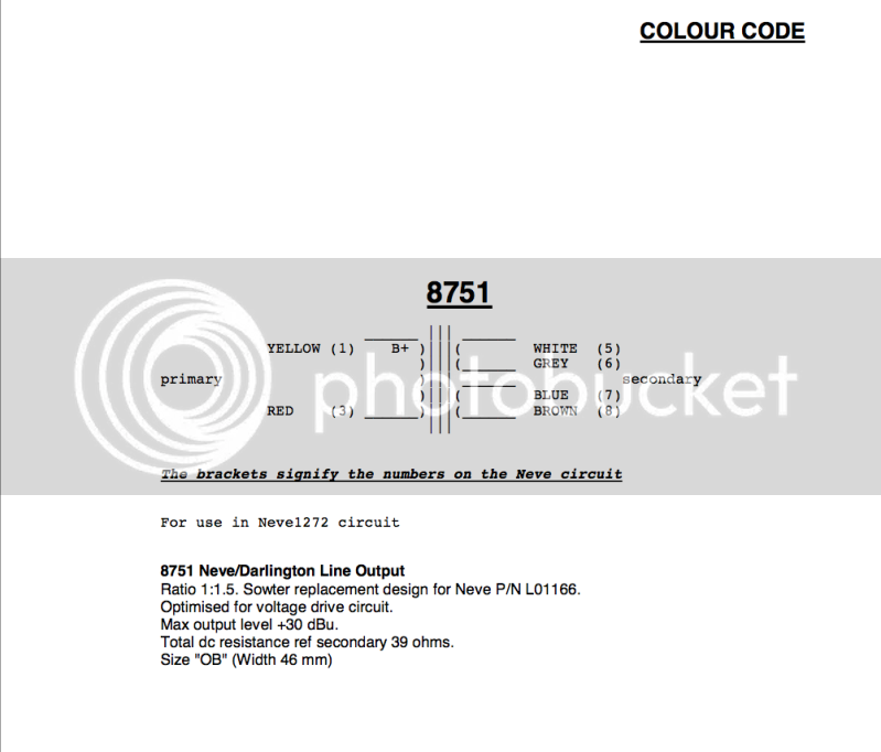
I doesn't work properly, of course. But how could it be that both transformers are fried? Am I hooking them up incorrectly? Below is a picture Sowter sent me for the transformer color-code and JLM's 1272 circuit. Do I need to wire a cap [.01] and resistor [1k5] to get these to work?

If you look at the earlier pictures I attached you will see that I wired Yellow [ + ] and Red [ - ] to Primary, and White/Grey [ + ] and Blue/Brown [ - ] to Secondary. Have I missed something?

Thanks!
 

Attachments

  • Screen Shot 2012-10-01 at 5.24.12 PM.png
    Screen Shot 2012-10-01 at 5.24.12 PM.png
    415.7 KB · Views: 41
Dan unless I am missing something really obvious you are using the wiring info.  The 1272 does not have anything in common with the output stage of the 33609.  The 1272 uses the LO1166 output transformer which is a gapped transformer to allow DC to flow through the primary.  The original 33609 used the LO1173 and a different gain stage.

You need to refer to the 33609 manual, not the 1272 which is a different circuit.

 
Here's the hookup guide for that transformer.

http://i25.photobucket.com/albums/c95/fmoscowitz/9145.jpg

It's really not the correct transformer but it should work.

Regards,
Mark
 
ruairioflaherty said:
Dan unless I am missing something really obvious you are using the wiring info.  The 1272 does not have anything in common with the output stage of the 33609.  The 1272 uses the LO1166 output transformer which is a gapped transformer to allow DC to flow through the primary.  The original 33609 used the LO1173 and a different gain stage.

You need to refer to the 33609 manual, not the 1272 which is a different circuit.

I am referring to the 33609 manual. And I'm not a fool. I know the 1272 is a different circuit. The reason I mentioned the 1272 is because the output transformers I am using are originally designed to be used as L01166 replacements. These were not my first choice but they came with the parts kit I purchased from a groupdiy member a while back…

Again, I mentioned the 1272 because I'm a noobie and hooking this xformer up the way it says in the 33609 schematic doesn't work. If you refer to sowters' hookup page [I posted it 2 posts back on this page] you'll see it says "for use in Neve1272 circuit". So… my question to everyone is: can I hook it up for use in the 33609 output stage?

Thanks! 


Biasrocks said:
Here's the hookup guide for that transformer.

http://i25.photobucket.com/albums/c95/fmoscowitz/9145.jpg

It's really not the correct transformer but it should work.

Regards,
Mark

Thank you Mark. If you look 1 post back on this page, you'll see I posted the correct Sowter hookup page for the 8751. The link you attached is for the 9145. Different color-code, etc.

Thanks anyway!
 
I feel like I have officially given up on this! I don't know if buying two more o/p xformers will fix the problem, and those cost a lot.

Attempting to complete it is just taking too much time out of my life. It's disappointing because it was a very big investment for me both in time and money. I can't get the time back, but I will try and recoup some costs. If anyone is interested in purchasing my non-functional 33609, just send me a message.

Dan P.
 
Before selling your unit or buing new trannies, take a multimeter at 200 Ohm range; check trannie's DCR; check if windings are connected correct etc.
At output transformer 4 pin connector, you should measure about 10 ohm between 1-2 and about 20 ohm between 3-4.
If you have inductance meter, worthy to check inductance of primaries and secondaries when the trafo is out of circuit.
You're smart guy and will find where the surprise found.
 
As well. I saw something suspicious at the picture. Please correct me if I am wrong...
If this is your trannie:
http://i25.photobucket.com/albums/c95/fmoscowitz/9145.jpg

EDIT: I remembered 2 different trannies were mentioned. Haha!
 
Igor said:
Before selling your unit or buing new trannies, take a multimeter at 200 Ohm range; check trannie's DCR; check if windings are connected correct etc.
At output transformer 4 pin connector, you should measure about 10 ohm between 1-2 and about 20 ohm between 3-4.
If you have inductance meter, worthy to check inductance of primaries and secondaries when the trafo is out of circuit.
You're smart guy and will find where the surprise found.

Thanks Igor. I checked the trannies as you suggested and I didn't get those readings. I got no resistance between 1-2 and 3-4. Instead I got 18.6 ohms [close to 20!] between 1-3 [the +] and nothing between 2-4.  :-\

 
hi, having the Carnhill output tranny here, on the schemo is one pole on each side marked with a dot, on PCB there is +/- markered for pri/sec , how do i connect them ?  .and, do i have to ground the middle (ground) pin somewhere ?

this will be the last thing i have to do , then i can fire up after 3 years of building,parts sourcing, loosing parts again in magic black holes that are around everywhere on my table.. ::)
 
ok i can see the markings in the 33609 schemo also. the original tafo is grounded here. so i should ground my carnhills ( suggestions for best place ?)
as we are at grounding, should i just solder a small piece of wire from the upper pad on the psu to the pad on the downside through the hole in the pcb here ? as i see one is power ground  and one is audio´´ ground ? >> from there one wire to star ground ?
thanks
axel
 
Axelerator said:
hi, having the Carnhill output tranny here, on the schemo is one pole on each side marked with a dot, on PCB there is +/- markered for pri/sec , how do i connect them ?  .and, do i have to ground the middle (ground) pin somewhere ?

this will be the last thing i have to do , then i can fire up after 3 years of building,parts sourcing, loosing parts again in magic black holes that are around everywhere on my table.. ::)

Dot is used to be +
Ground pin - to chassis if chassis.
 
Axelerator said:
ok i can see the markings in the 33609 schemo also. the original tafo is grounded here. so i should ground my carnhills ( suggestions for best place ?)
as we are at grounding, should i just solder a small piece of wire from the upper pad on the psu to the pad on the downside through the hole in the pcb here ? as i see one is power ground  and one is audio´´ ground ? >> from there one wire to star ground ?
thanks
axel

Yes. Yes.
 
Igor said:
Before selling your unit or buing new trannies, take a multimeter at 200 Ohm range; check trannie's DCR; check if windings are connected correct etc.
At output transformer 4 pin connector, you should measure about 10 ohm between 1-2 and about 20 ohm between 3-4.
If you have inductance meter, worthy to check inductance of primaries and secondaries when the trafo is out of circuit.
You're smart guy and will find where the surprise found.

Thanks Igor. I checked the trannies as you suggested and I didn't get those readings. I got no resistance between 1-2 and 3-4. Instead I got 18.6 ohms [close to 20!] between 1-3 [the +] and nothing between 2-4.  :-\

Any ideas?
 
Ohho ;)
If you got no resistance between 1-2 and 3-4, trannies are connected wrong way. You need trannie with 8 db stepup from Carnhill (audiomaintenence),
it was written many times on this thread. Well, I don't know what trannies you have and messed by previous posts.
A link to trannies datasheet is welcome.
If there is no datasheet and there is unknown tranny which can fit (maybe) - let's take a chance.
Check your trannies with ohmmeter. Find the windings ends. Write down the DCRs and wire colors.
Primary's probably will have less resistance than secondarys. Probably primarys will have equal DCR and secondarys will have equal DCR.
Check the inductance of windings with inductance meter, if have it.
If no - buy Carnhills or other TF12009 equivalents (better money investment for now than inductance meter,
if you don't plan to roll your own inductors or check trannies/inductors in future).
Mind output trannie should be +8 db (or about 1:2.6 stepup), or 70 Ohm:600 Ohm.
If have an inductance meter, write down each winding dcr and inductance; than connect primary's in series - the inductance readings shoud be 4 times higher than one primary if connected in series in phase or almost zero if connected in series out of phase. Same way check phasing of secondary's.
This way you know where each winding is and its polarity.
Now, connect everything in phase in series and you know phasing of primarys versus secondarys. Higher reading is in phase, smaller readings is out of phase.
Than you can connect the trannie right way and pass to next stage of troubleshooting (80% from my point of view of logic, statistics and positive negative thinking),
or, if you lucky enough not messed anything, 20% - to calibration of unit with oscilloscope and oscillator.
Good luck than and write down trannie investigation results - neither I am VERY curious, but interesting, what's going on here ;)

Ah yep, and last edit, by windings connected in series in phase mean: /+windingA-/(connection)/+windingB-/; measure between +windingA and -windingB
 
Igor said:
A link to trannies datasheet is welcome.

here's all the info I could find on the Sowter 8751

Screenshot2012-10-17at75029PM.png


Igor said:
Check your trannies with ohmmeter. Find the windings ends. Write down the DCRs and wire colors.
Primary's probably will have less resistance than secondarys. Probably primarys will have equal DCR and secondarys will have equal DCR.

Ok. I checked and got this:

Yellow & Red: 20 ohms
Brown & Blue: 24 ohms
Grey & White: 24 ohms

that's all I could get. It looks like I'm missing a primary?  ??? The data sheet says Yellow and Red are the primaries… confusing!

Igor said:
Check the inductance of windings with inductance meter, if have it.
If no - buy Carnhills or other TF12009 equivalents (better money investment for now than inductance meter,

I only have a cheap-o multimeter and it doesn't test inductance! Should I just buy the Carnhills?

Igor said:
Ah yep, and last edit, by windings connected in series in phase mean: /+windingA-/(connection)/+windingB-/; measure between +windingA and -windingB

If I'm not mistaken, this is how I had the secondaries wired [Brown/Blue & Grey/White]. Was this incorrect?

 
If I'm not mistaken, this is how I had the secondaries wired [Brown/Blue & Grey/White]. Was this incorrect?
[/quote]

1. Transformer Typ
this (sowter 8751) is not the correct transformer. The Sowter 8751 is a replacement part for the LO1166 (DC gapped, see the B+ marking on the primary) with a ratio of 1:1.5
anyway... if wired correct it should pass audio in your 33609 derivat.

2. Transformer windings
The Transformer have ONE primary winding and TWO secondary windings
Yellow(1) / red (3) are the PRIMARY windings. Yellow is +, red is -.
White (5) / gray (6) is the FIRST SECONDARY winding, white is +, gray is -.
Blue (7) / brown (8 ) is the SECOND SECONDARY winding, blue is +, brown is -.

3. Wiring
for a step up Setup (1:1.5):
Pri: Yellow + and Red -
Sec: White +, gray and blue linked, brown -

hope it helps
 

Latest posts

Back
Top