Official C12 Clone - Build and Support Thread

GroupDIY Audio Forum

Help Support GroupDIY Audio Forum:

This site may earn a commission from merchant affiliate links, including eBay, Amazon, and others.
mica said:
Ohh so i need to run a new wire between FB and RB on the capsule?

I prefer to do it in the mic instead of physically soldering on the capsule in case I want to re-purpose the capsule for a 251, etc. but either way the backplates need to be tied together either at the capsule or where they connect to the mic.
 
So just to be 100%: I can do a wire between the turrets FB and RB on the PBC where the two capsulewires are connected with the same result right?

/M
 
hey there - quick newb question - can I use a microphone parts k67 to test/bias my matachung c12? (before I stick Eric's capsule in)
-thanks!
Dan
 
friesdan said:
hey there - quick newb question - can I use a microphone parts k67 to test/bias my matachung c12? (before I stick Eric's capsule in)
-thanks!
Dan

I would say no. these 2 capsules have a different capacitance and I'm sure the mics have a different polarization voltage.
However, I could be wrong. It def wouldn't sound very good. Those RK67s are nothing like the HK-12s
 
wave said:
friesdan said:
hey there - quick newb question - can I use a microphone parts k67 to test/bias my matachung c12? (before I stick Eric's capsule in)
-thanks!
Dan

I would say no. these 2 capsules have a different capacitance and I'm sure the mics have a different polarization voltage.
However, I could be wrong. It def wouldn't sound very good. Those RK67s are nothing like the HK-12s

Actually  I not only did all of my testing with the stock Alctron K67 type capsules, they sounded pretty decent.  Get it all working 100% and then drop in the good stuff.  Check and trim all voltages, and then impress your friends.  ;)
 
friesdan said:
hey there - quick newb question - can I use a microphone parts k67 to test/bias my matachung c12? (before I stick Eric's capsule in)
-thanks!
Dan

Yes, you can.  Keep in mind that the C12 circuit is essentially "flat response", and the 6-8kHz peak on a K67 may not sound the best to your ears.

However you can use it to get the mike functional and then sub in a different capsule later:  neither the polarization voltage nor the tube bias care what kind of capsule is installed.
 
Thanks Matador - the idea is to protect my $450 6 month investment ;)
now should I start with that NOS tube installed too? or maybe swap in an ax7 from my mesa amp...
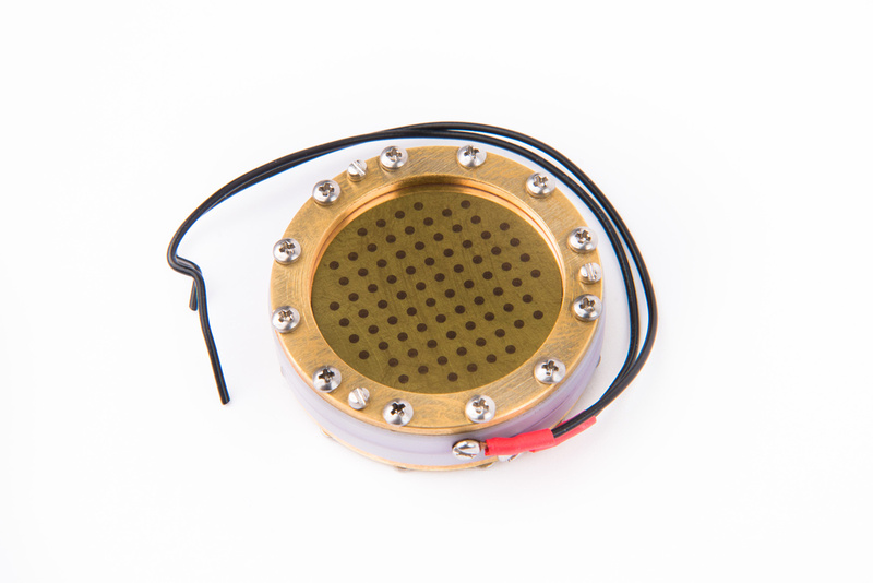
 
friesdan said:
Thanks Matador - the idea is to protect my $450 6 month investment ;)
now should I start with that NOS tube installed too? or maybe swap in an ax7 from my mesa amp...

The B+ portion of the power supply is passive, so you need to use the same type of tube that you end up using.  If 6072A, I recommend using an Electro Harmonix tube as they are low cost and are more than adequate for function testing.  Otherwise, we have made provisions for 12AT7 swap in the kits.  If that is what you are using, the options for a test tube are numerous.

A 12AX7 would be hard to dial in without resistor value changes in the PSU and in the mic.

 
Greetings to all,

Questions ???

I should strap a 180K ohm resistor across the B+ and ground to calibrate the B+ to 195V
and the Bias to -1.03V which will approximate the load of the (mic’s amp circuit) on the
power supply “right ?”.

However; this build is using the Tim Campbell capsule with the GE five Star 6072A tube.

I am using the budget 34mm edge terminated capsule with the Mullard 12AT7 Tube.

What are my correct (optimal) voltages?,

Am I shooting for (120V / B+) and (-1.0V / Bias) just like the CT12 capsule & the 6072A tube,

I think not!, I’m pretty sure my optimal voltages are different for the B+ and the Bias.

Also, where's the best place to strap the 180K ohm resistor,

Into the 7 Pin xlr connector on the front of the power supply ?

or maybe at the 5 connector terminal block on the power supplies PCB ?

or just twist the 180K ohm resistor around my voltmeters probe tips ?.....
 
Eric Heiserman's HK12 capsules are in. . . testing under way.

p358481415-4.jpg
 
zandru said:
I am using the budget 34mm edge terminated capsule with the Mullard 12AT7 Tube.
What are my correct (optimal) voltages?,
Am I shooting for (120V / B+) and (-1.0V / Bias) just like the CT12 capsule & the 6072A tube,

The B+ and bias voltages don't change...you should shoot for the same +120V and -1V...however, what does change...

zandru said:
Also, where's the best place to strap the 180K ohm resistor,

Into the 7 Pin xlr connector on the front of the power supply ?

I plug the resistor right into the 7-pin XLR connector....

However for a 12AT7, 180K is the wrong value.  The 12AT7 idles at a much higher bias current (about 1.1mA) than the 12AY7/6072A (about 0.7mA).  This implies a test resistor of about 110K, not 180K.  100K should be close enough.
 
Hey Mat.  I'm sure it's been covered but I can't for the life of me find it.  What was the determining factor to go for -1V for the bias voltage rather than the original spec. -1.1V and how would that affect the final sound.  The reason I ask is because two of my matched pair (capsules/tubes/etc.) sounded different and one sounded slightly more vintage.  When I re-biased them for the matched tubes I noticed the bias had drifted below -1V on the one that was more "milky" while the second mic was still right at -1V and sounded much more open.

Is there a way to measure the exact bias each tube wants?  Can a .1V variance really produce an audible difference?  It's so difficult to test in application because it become impossible to maintain exact distance, performance dynamic, etc. between adjustments. 
 
Category 5 said:
Hey Mat.  I'm sure it's been covered but I can't for the life of me find it.  What was the determining factor to go for -1V for the bias voltage rather than the original spec. -1.1V and how would that affect the final sound.  The reason I ask is because two of my matched pair (capsules/tubes/etc.) sounded different and one sounded slightly more vintage.  When I re-biased them for the matched tubes I noticed the bias had drifted below -1V on the one that was more "milky" while the second mic was still right at -1V and sounded much more open.

Is there a way to measure the exact bias each tube wants?  Can a .1V variance really produce an audible difference?  It's so difficult to test in application because it become impossible to maintain exact distance, performance dynamic, etc. between adjustments.

Each tube will have a particular "optimum" bias point based on it's exact parameters (rp, gm, mu, etc) and the exact impedances that are connecting it in circuit.

The -1V point was my best swag based on the test tubes I installed in the dozen or so prototypes that were built and tested.  There is no "just one" bias point to cover every tube, just like there is no single source resistor to handle every JFET (since every JFET has a different gm, VGSoff, etc).

"Optimum" is also overloaded, as you can optimize for different things.  The C12 circuit is "middish" gain (like 8-10dB), and I think was optimized to larger signal swings at the grid to give more headroom for very dynamic capsules.  I think sensitive large diaphragm condenser capsules are capable of near 1V signal peaks on close-miked loud sources, so that was the optimization point I picked.

A -1V bias gives 2V peak-to-peak input signal swing (actually a bit more, since the tube will still function properly when the grid goes positive WRT the cathode), so that seemed like a reasonable range.

If you want to get super pedantic, you need to bias the tube just like a JFET:  with a maximal signal swing test.  You dial up the bias resistor to maximum, and inject a 100mV 1kHz sine wave and increase the amplitude until one side of the signal (measured at the plate) starts to squash out and distort (this will generally be the bottom half of the signal, where the grid is driven positive and then rapidly goes non-linear).  Then you lower the cathode resistor until symmetry is perfect again.  Then start increasing amplitude again.  You'll reach a point when as you increase the signal more, both the positive and negative peaks start to squash about equally.  This is the optimal bias point, where "optimum" means "maximum input signal headroom", and NOT maximum gain!

This circuit is very flexible:  you can lower the plate resistor which increases the current and increases the slop of the load line.  Gain drops, but you can move the bias point lower and the circuit can take even higher signal swings with no distortion.  I've used a 68K load resistance and a -1.5V bias point, and the circuit can swing 3V PTP.  It really didn't sound any different to me though (I may have not been really abusing the capsule, like close miking a kick drum from 6" away).

However -1V should work in Most CasesTM.
 
That was just the reply I was looking for.  Thanks for the detail Matador.  So it's really no different than biasing my preamps so that clipping is symmetrical.  I have noticed both my mics clip early on the bottom of the waveform.  Which voltage shifts it up?  + or -?  I guess if I get bored I can view the output of a 1KHz sine wave on a scope and adjust it in real time for symmetrical clipping.  I know I'm not clipping the mic but rather the AD, but the offset of the waveform causes it to clip prematurely if the levels get too hot.

Good stuff!  This is a great project and very informative thread.
 
Category 5 said:
That was just the reply I was looking for.  Thanks for the detail Matador.  So it's really no different than biasing my preamps so that clipping is symmetrical.  I have noticed both my mics clip early on the bottom of the waveform.  Which voltage shifts it up?  + or -?  I guess if I get bored I can view the output of a 1KHz sine wave on a scope and adjust it in real time for symmetrical clipping.  I know I'm not clipping the mic but rather the AD, but the offset of the waveform causes it to clip prematurely if the levels get too hot.

Good stuff!  This is a great project and very informative thread.

The circuit is inverting, so a clip to the bottom (voltage falling) means the current is rising, which means the grid is rising.  You want to make the bias more negative.
 
Matador said:
zandru said:
I am using the budget 34mm edge terminated capsule with the Mullard 12AT7 Tube.
What are my correct (optimal) voltages?,
Am I shooting for (120V / B+) and (-1.0V / Bias) just like the CT12 capsule & the 6072A tube,

The B+ and bias voltages don't change...you should shoot for the same +120V and -1V...however, what does change...

zandru said:
Also, where's the best place to strap the 180K ohm resistor,

Into the 7 Pin xlr connector on the front of the power supply ?

I plug the resistor right into the 7-pin XLR connector....

However for a 12AT7, 180K is the wrong value.  The 12AT7 idles at a much higher bias current (about 1.1mA) than the 12AY7/6072A (about 0.7mA).  This implies a test resistor of about 110K, not 180K.  100K should be close enough.

muchas gracias Matador, For this highly valued Intel. In my gratitude; I will send you twelve of my finest Picadors.


Sincerely Zandru....
 
Back
Top