P2P Redd 47 - a few questions

GroupDIY Audio Forum

Help Support GroupDIY Audio Forum:

This site may earn a commission from merchant affiliate links, including eBay, Amazon, and others.

letterbeacon

Well-known member
Joined
Jul 12, 2009
Messages
642
Location
London, UK
I thought I'd start a new topic as the previous one was more about finding a schematic, whereas this one will hopefully be a discussion about building a REDD 47 pre amp point to point.  This is my first point to point project so I have a few questions, some that may be obvious to more experiences posters, so please be patient!

It looks like the original schematic, dated 01/10/1951, is available here: http://www.sowter.co.uk/schematics/EMI-REDD47.pdf and there is a redraw with component layouts here: http://www.twin-x.com/groupdiy/displayimage.php?album=322&pos=0

I've compared the original to the redraw and the only error I can see on the redraw is that the resistor on the E88CC should be 8k2 rather than 82k.

Comparing the schematic to the component layouts, I have noticed a couple of descrepencies that I'd like to run by you guys. 

- The input transformer on the component layout has a 20pf cap with a 32k resistor in series where the schematic calls for a 100pf with a 100k resistor in series.  Is that because whoever drew the component layout is using a Cinemag transformer?  What are the purposes of that capacitor and resistor?

- The power supply section calls for two 1N4007 diodes on the component layout, but they aren't on the schematic.  Is that because originally the power was already rectified DC from the desk?

- On the schematic, the two 47uf caps have their positive leads connected together as well as by a 1k 2W resistor, however on the layout they're only connected via the resistor.  Is there a reason for this, or is it a mistake?

Do you think I could run two pre amps from the one power supply?

That's it for now - thanks!
 
Nothing much to add except that if you will make a p2p or turret board layout at some point to please share it with the rest of us once you've finished it. Might prove usable to others who would embark upon the same journey. I might take apart / sell my drip versions and make p2p / turret versions to have more in the same case.
 
Yes I will of course share the layout with the DIY community!

I've been trying to figure out the best way to get phantom power into the case.  At the moment I'm thinking of having another smaller power transformer in the case and rectify the 48v from that, but is there a more elegant solution?

I'm planning on using the Hammond 370bx as the power transformer.  It has the 550V CT @ 58ma, 5V CT @ 2A, 6.3V CT @ 2A.  Is it possible to get 48vdc from one of those secondaries?
 
I'm curious to know what type of resistors and capacitors they used in the REDD 47 pres.  The schematic is dated 1st October 1959 but it calls for 'high precision' 2% tolerance resistors.  Would that have been metal film resistors?  I didn't know they had those back then!

Also, the capacitors used - apart from the electrolytics and where it specifies silver mica - would they have been film caps or paper in oil?

Thanks!
 
letterbeacon said:
- The input transformer on the component layout has a 20pf cap with a 32k resistor in series where the schematic calls for a 100pf with a 100k resistor in series.  Is that because whoever drew the component layout is using a Cinemag transformer?  What are the purposes of that capacitor and resistor?
This is called a Zobel circuit. It is designed to compensate the self-resonance of the input transformer, making the square-wave response nicer and taming the supersonic hump. Each xfmr needs a different compensation.
- The power supply section calls for two 1N4007 diodes on the component layout, but they aren't on the schematic.  Is that because originally the power was already rectified DC from the desk?
Good guess!
- On the schematic, the two 47uf caps have their positive leads connected together as well as by a 1k 2W resistor, however on the layout they're only connected via the resistor.  Is there a reason for this, or is it a mistake?
This looks like a mistake, unless it is there to offer the option to alter the B+ voltage. I would not join them directly.
Do you think I could run two pre amps from the one power supply?
The transformer would need to be dimensioned accordingly, which shouldn't be difficult considering the modest requirements of a single unit.
 
http://www.groupdiy.com/index.php?topic=7292.0

this thread can help you out a bit.guitarmaker has shared his layout in the past why not try him?
 
8) 8) 8) 8) 8) 8) 8)
 
Thanks, abbey road, for those answers - very imformative!

Thanks for the link seavote - that thread didn't come up when I searched for it on here for some reason.
 
Interesting... I linked to them in my first post (well, it was a layout, I'm assuming it was his) and that's not working now either.  Do you think someone's deleting them because of this renewed interest?
 
it could be costing somebody unwanted bandwidth... ?

EDIT: You'll have to contact guitarmaker...seems he hosted them on his website. I'm sure he'll upload them again or email them.
 
Regarding, the separate power supply, as I remember the EMI 47's gave off far more heat than the V72's they replaced so they had to have a remote power supply to keep the desk cool.

I made one using 2 sowter 4:1 TX's, they swing both ways, if you pardon the expression, they were both 7:1 on the original.

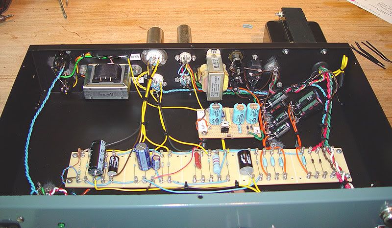
Here are some pics showing the p-p layout I used.

seosi0.jpg


Power supply in next compartment

34ilir6.jpg


Front Panel

2cbpdd.jpg


Back

zmcgno.jpg


This was the spec I measured:-

R47  Specification (R.E.D.D.47)


Test Conditions

Signal Generator output Impedance 600 ohms.

200 ohm load resistor across input terminals.

3.3K load resistor across output terminals.


Gain Switch Input max. Output max Gain

34dB 157mV 7.5V 47.8x

40dB 92mV 9.0V 97.8x

46dB 53mV 10.0V 188.7x


Gain Switch Input max. Output max Gain

34dB -13.9dBu 19.7dBu 33.6dBu

40dB -18.5dBu 21.3dBu 39.8dBu

46dB -23.3dBu 22.2dBu 45.5dBu


Signal :Noise Ratio.


Gain Switch mV p-p mV rms S:N ratio E.I.N.

34dB 0.095mV 0.033mV 87.3dB -120.9dBu

40dB 0.22mV 0.080mV 79.7dB -119.5dBu

46dB 0.5mV 0.177mV 72.8dB -118.3dBu

This mic-pre performed very well but I got converted to no feedback amps in the end, having said that the Beatles used these amps so who am I to judge?
best
DaveP
 
was hoping you guys would get around to this.  but i contacted guitarmaker he is ok with me sharing his layout. he also has a layout for the PSU he used but a lot of members used a modded gyraf G9 PSU.  as for 48V  phantom,phase etc id use this:
http://www.jlmaudio.com/shop/index.php?_a=viewProd&productId=8

reddamplayout.jpg


reddpowerlayout.jpg


redpic1.jpg


DaveP said:
Signal :Noise Ratio.


Gain Switch mV p-p mV rms S:N ratio E.I.N.

34dB 0.095mV 0.033mV 87.3dB -120.9dBu

40dB 0.22mV 0.080mV 79.7dB -119.5dBu

46dB 0.5mV 0.177mV 72.8dB -118.3dBu
This is not really normal. As the gain increases, the EIN should decrease. That indicates there is a source of constant noise located after the input stage; looking at the layout, I reckon it may well be the xfmrs picking up the mains xfmr stray field. It would be interesting to have a better analysis of the noise spectrum.
This mic-pre performed very well but I got converted to no feedback amps in the end, having said that the Beatles used these amps so who am I to judge?
The Beatles were actually quite passive in the choice of these preamps; in fact even Norm Smith or Geoff Emerick didn't have their say about the equipment that was put in their hands by EMI's technical directors. Which just shows that talent is much more important that equipment.
 
letterbeacon said:
- On the schematic, the two 47uf caps have their positive leads connected together as well as by a 1k 2W resistor, however on the layout they're only connected via the resistor.  Is there a reason for this, or is it a mistake?
As I surmised, the manual confirms that it is an option allowing it to be used with a different PSU.
 
DaveP - That looks great, thanks for the pictures!

Seavote - Yes that's the layout I linked to in my first post.  Is that your build pictured?  Looks good!  I'm thinking of hanging the transformers out the back of the case along with the tubes to free up space in the case.  Is their a risk of noise from the PT if I do that (I'll be using a Hammond too)?

Are you using the 50VAC winding on the Hammond for the AC/DC board?  Any noise issues with that?

Thanks!
 
the project photo posted is not mine,i havent gotten around to a redd47 build. i  believe the photo is from guitar maker.
8) 8) 8) 8) 8) 8) 8) 8) 8) 8) 8) 8) 8) 8)
 
JayDubrek said:
On the layout posted above there's a 100mF Elec with the +ve side unconnected?

Looks like it should be connected to the top leg of the 200R resistor next to it.  It's supposed to tie the E88CC's cathode to ground.
 
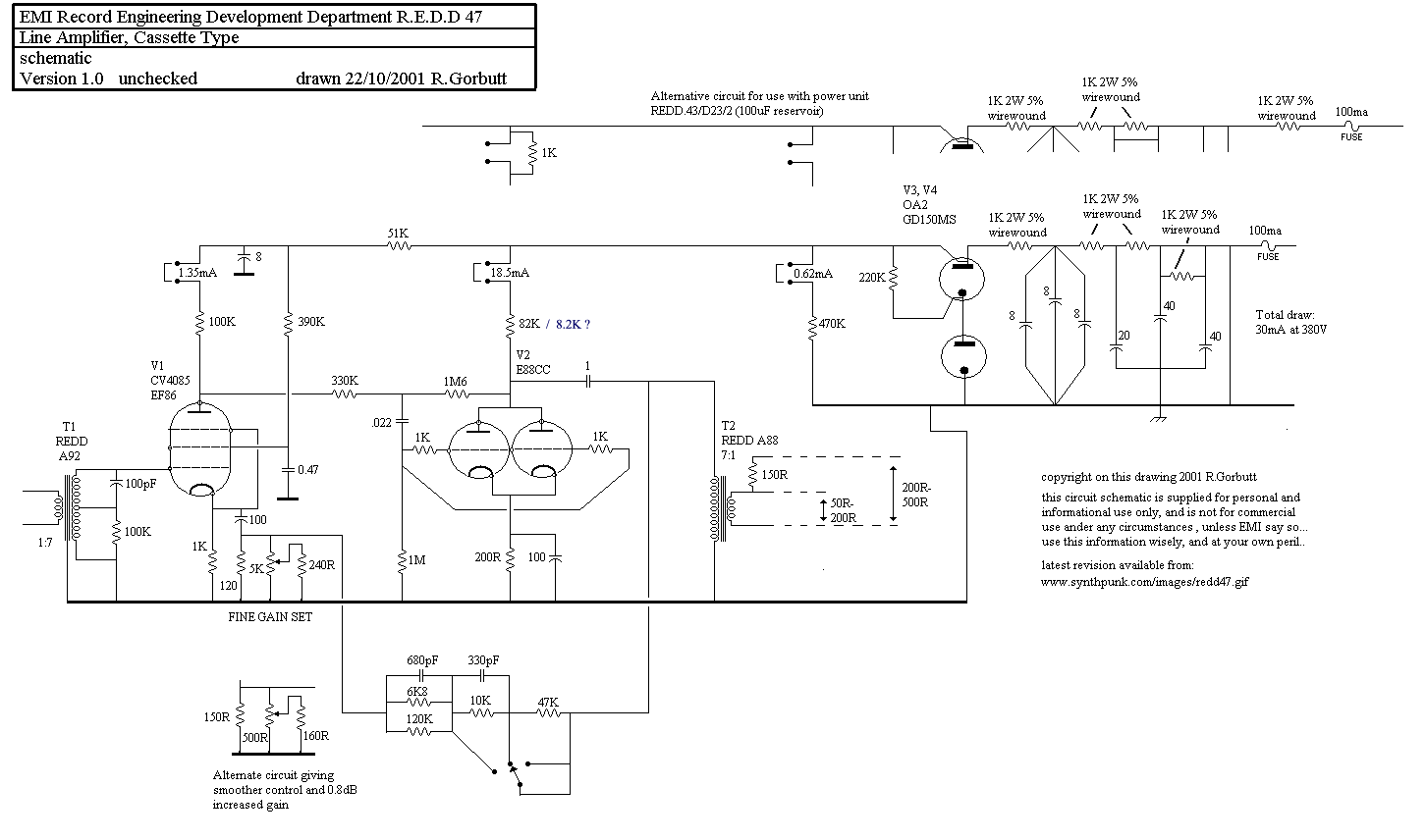
Here's the schematic for the REDD 47:
redd47.gif


If I wanted to increase the gain available, is it just a case of changing the values of the capacitors and resistors on the selector switch, or maybe adding another couple of point to it?  I've read that the V72 have a very complicated method of controlling the gain, and messing with the design isn't recommended, but is it the same with the REDD 47?

Tubes are still relatively new to me, and I'm still trying to get my head round them, so any help would be much appreciated!
 
You can try.
You can reduce the overall NFB by increasing the resistance of the FB loop. Actually, the selector switches between 6k, 16k and 63k. You could add a fourth position, with an additional resistance (about 100-200k), but the open-loop gain may not be large enough to increase noticeably the gain, and there would be the side effects of reduced bandwidth and increased distortion.
You may also have to increase the gain of the output section, which is governed by the 330k (input) and 1M6 (FB) resistors; you may try increasing the 1M6. This would increase the open-loop gain.
 
Back
Top