Ribbon mic test setup - what's wrong with this?

GroupDIY Audio Forum

Help Support GroupDIY Audio Forum:

This site may earn a commission from merchant affiliate links, including eBay, Amazon, and others.

rubinstu

Active member
Joined
Jan 10, 2019
Messages
37
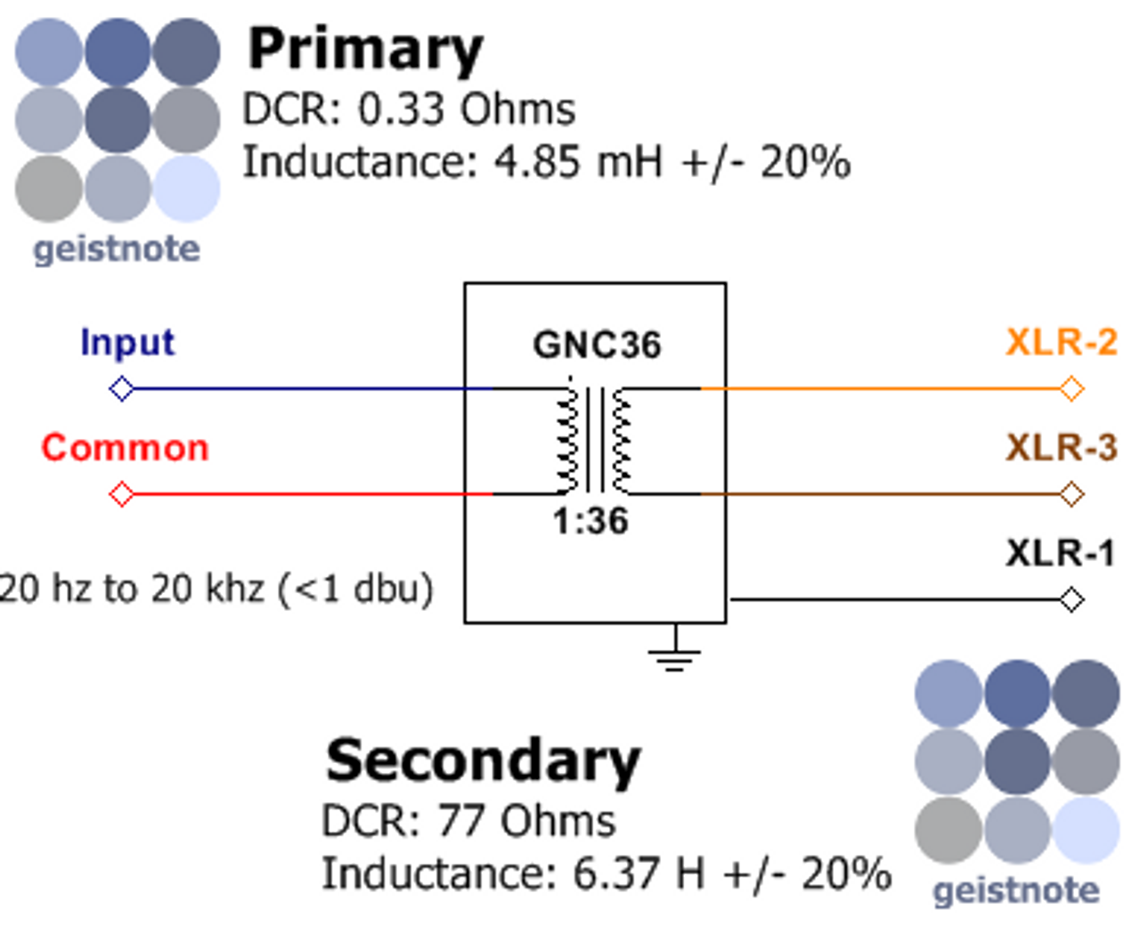
All, the photo below shows my first ribbon mic in a test configuration. If it's not clear from the drawing, I have each side of the motor connected to the primary of the transformer, and the secondary loaded with a 91K ohm resistor. The scope lead is also connected to the secondary. The transformer ground (at least I think that's what it is, the black wire) is not connected to anything.

Transformer is Geistnote GN-C36, 1:36 turns.

The problem is that I'm not seeing any signal at all on the scope. I can make noise, clap, etc., and I get no response on the secondary. (I don't get any response on the primary either, but I assume that's a pretty small signal even when working correctly.)

Ribbon is not touching the magnet.

When disconnected from the transformer, there is about 2-ohms between the two outputs of the motor (so there is a good connection between the ribbon and the wiring).

Shouldn't I be seeing some action on the scope?

All input is appreciated! Thanks!

1672117008101.png
 
Uncertain connections on the breadboard itself?

And why the two yellow wires coming from the top of the motor? Might they be equating to a shorted turn, being around those magnets?
 
The loop is commonly used to keep the resistance in the wiring down ,
Physically the wires causes an effect sonically , if its balanced on either side of the ribbon it might be better ,
Some ribbon mic just use the case as the return from the far end of the ribbon , not a good idea in my experience .

There must be some thing simple wrong in the above set up , get rid of the bread board , twist the wires together as required , no need for the 91k resistor for now either .
 
Last edited:
I would forget the breadboard and solder the connections.
At such low impedances any extra resistance will at least give misleading results.
Is the connection of the transformer wires correct?
 
Uncertain connections on the breadboard itself?

And why the two yellow wires coming from the top of the motor? Might they be equating to a shorted turn, being around those magnets?
Electrically speaking, the breadboard connections are what I expect them to be. That is, the contacts exists where I want them, and do not exist where I do not them. But, I could still be doing something wrong.

As for the two yellow wires, I've seen this on many (if not most) DIY ribbon designs. My assumption is that you two wires for general symmetry in the design (maybe, as some previous commenter stated, some acoustic reason). From a simple DC electrical point-of-view, they can be seen as one wire.

Here is the wiring diagram for the transformer. I'm pretty sure I got it right, but a second opinion is always good.
gnC365__47168.1637842248.png


I'll retest without the breadboard, load resistor, etc. and report back.
Thanks, everyone!
 
I undid the prototype PCB and soldered the connections and voila it's working! The levels are low, but definitely serviceable. We used my son's Focusrite interface to make a quick guitar recording and it sounded pretty good. The main issue is that there's a lot of noise, but there's no EM shielding or anything yet, so I'm not worried.

Did you check the transformer windings for their resistance?
I did the other day, but did not write down the measurements. It was something like 2-ohms on the primary and 77-ohms on the secondary, which was pretty darn close to the published 1:36 turns ratio!

Don't judge the playing, but I attached a quick sample of the recording.

Thanks for the tips!

1672182734853.png
 

Attachments

  • First_test_two_tries_sample_20221227.wav
    1.8 MB

Latest posts

Back
Top