The official GroupDIY 511 Help & Support Thread

GroupDIY Audio Forum

Help Support GroupDIY Audio Forum:

This site may earn a commission from merchant affiliate links, including eBay, Amazon, and others.
livingnote said:
Oh - it's "Gleitzeit" through approx. Saturday morning.
cool. have to prepare some plug-in files ;D

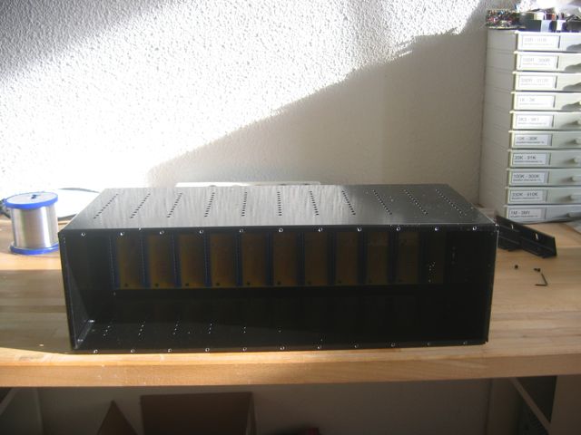
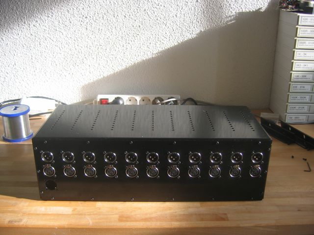
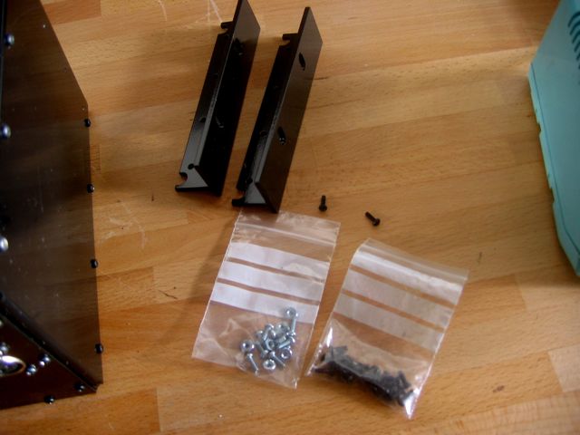
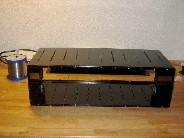
back to the metal work,
you screw the sides from the outside:

IMG_5894.jpg


with the same screws out of the bag you used for the Neutriks (m 2.5 this is)
 
Hi Volker,
got two little questions, which I thought I ask here for the benefit of other builders:

1. how did the screwing-in-of-XLRs FIRST work for you? easy to line up the pins on the PCB afterwards? or would you prefer the sahib-one-pin-solder approach in hindsight?

2. on the grounding scheme: what if a mic pre-amp needs to provide phantom power? is it enough to have pin 1 on the chassis or does it also need to be connected to PSU ground? I understand removing pin1 from the chassis is not possible with the included XLRs?

cheers
brio
 
briomusic said:
1. how did the screwing-in-of-XLRs FIRST work for you? easy to line up the pins on the PCB afterwards? or would you prefer the sahib-one-pin-solder approach in hindsight?
both ways worked fine. I did assemble one prototype PCB completely without having any metal work, and I had no problems to screw the metal down.
the one I assembled for this thread, I just snapped the Neutriks in, screwed them down to the metal and soldered.
both ways worked fine for me, and sahibs way will work too.

briomusic said:
2. on the grounding scheme: what if a mic pre-amp needs to provide phantom power? is it enough to have pin 1 on the chassis or does it also need to be connected to PSU ground? I understand removing pin1 from the chassis is not possible with the included XLRs?
the XLRs we use have pin 1 connected to the chassis. haven't measured yet if this is enough connection since it is powder coated. however I would do the pin 1 to chassis link.
the PSU connector has separated connections of ground and chassis going to the PSU PSB.
the PSU PCB has separated connections from ground and chassis.
connect both together at one point in the PSU Chassis (together with the safety pin from your IEC) at one point and you should be fine.
 
hmmm still struggling at step 1  :'(

I did buy these http://www.conrad.de/ce/de/product/737079/STIFTLEISTE-EINREIHIG-36-POLIG-RM254 from conrad, but the solder side pins are a little too short and half of them fell back out...
for the ones that are staying in I am now paranoid that they don't have proper contact  :-\

I had some of these http://www.banzaimusic.com/Two-side-pin-strip-20P.html left which are longer on the solder side, they work fine. but banzai has €30 minimum for pick up orders now. haven't sent off my RS order yet, but of the 5 gazillion options that come up in their grid, none seem to have the elongated pins on the solder side.

unless anyone has a trick to make the solder flow into the pcb holes....?
 
brio,

put the jumpers  (the more the better).
cover the top with some sort of form material, not too soft, but soft enough the pins can go in.
reverse the backplane, nothing should fall out.
important is a hot enough soldering iron, try to touch the pins with the tip (they are only 0,5mm inside, it is possible).
add (enough) solder. works fine ;)
and you won't have to cut down the leads ...
 
You can usually push the pins down farther with a needle nose pliers and minimal force, one at a time. Just need to make sure the overall length of the pin is long enough for the shunt jumper pins on the other side. 3M has the largest variety State side IIRC.
 
[silent:arts] said:
important is a hot enough soldering iron...

I just wondered how hot it should be ? As XLRs are flush the pcb , have you got a special technic to solder them properly?(Dumb question , but I do not want to fail something in the mounting processus!)
 
My Weller WECP-20 is in the middle of 300 % 350 Degree of Celsius, I never measured how hot this is in reality ;)
I still don't use RoHS lead free solder  :eek: [don't tell anyone]

for the XLRs it is the same like with the jumpers:
hit the pins (you can reach them), add solder.

the solder points are all thru plated, this is no problem.

even the 50 pin SCSI headers on my prototype worked and measured fine, and there you have no chance to hit the metal pin in a 3mm PCB :)
 
Great , thanks for the "tips"...
Where should I claim for the missing Gummibärchen ???  ;D ;D ;D ;D
 
RedNoise said:
Where should I claim for the missing Gummibärchen ???  ;D ;D ;D ;D
will add some with your PSU order ;D ;D ;D

for the soldering of the headers and XLRs I will try to make some photos,
sadly this has to wait at least until wednesday :mad: :eek: ::)
 
Hi All

What is the part # for the 7 pin neutrik power connector. Does it come in the kit? I read some post on the topic but they sounded unresolved.

James 
 
http://www.groupdiy.com/index.php?topic=33849.msg461703#msg461703

(I'm currently sourcing parts as well - otherwise I wouldn't have a clue ;)

hth, christoph
 
Started soldering mine last night. All going well so far, which for a noob like me is saying somehting.

Three simple questions:

1. What is the specification for the pin headers I should buy for the jumpers?

2. What are the two separate rows of two holes at the top of the board for?

3. What socket do I need to buy to solder into those?

THis project is SO great. Thanks to all of you who have made it possible.

 
Back
Top