the Poor Man 660 support thread

GroupDIY Audio Forum

Help Support GroupDIY Audio Forum:

This site may earn a commission from merchant affiliate links, including eBay, Amazon, and others.
Thanks Alex,

Paralled 680K onto R7, actually lost a little voltage at the 245V out, ended up being 216VDC. Nothing smoked, good sign. I then added the 2 x 6BC8 back in, voltage drops from 216VDC to 142VDC.

Thanks for the offer to tech the board, I'd never let you do it for FREE, I owe you at least a case of beer for your help thus far!

I'm heading to NYC in a week, the unit is heading to by friend in Nashville. I know Analag is in NYC and then there is Gus in NJ, I'll try reaching out to them and see if they'd be willing to look at it and repair it there. The shipping costs of getting it insured and courier via FedEx or UPS from South Africa is going to be over $500 so it's cheaper to take it with me to NYC and have a tech look at it that end.

If it all comes to nought then I'll happily ship the board to you, but I'd pay you for you time, you've earned it, I REALLY can't thank you enough!

Matt
 
Cool, but did you measure the voltage at top of R6 ?

Anyway, sounds like that's not going as I expected!
 
Just did, it's increased from 93V to 101V, which means it's sitting at the same as voltage as D7 now, so I guess we need to lower the parallel resistance to get it above 101V? I guess seeing the voltage go from 93V to 101V is a good thing in this case!

It's beginning to seem my my power trafo might be under powered?

Cheers

Matt

alexc said:
Cool, but did you measure the voltage at top of R6 ?

Anyway, sounds like that's not going as I expected!
 
Well that's what I was looking for, but needs to be 0.6V higher than zener, so still not conclusive.
Next stop would be 600K or so in parallel. Least nothing is burned.

No - I don't think your traffo is underpowered, just .. different with a lower B+ resulting, meaning some adjustment of stuff is required.

I'd probably stop there - I'm not fully up on mosfet series pass regulator circuits, although I'm boning up now.
There's an element of 'bootstrap' startup that I have to think about - how the thing gets going to steady state ..

This is why I gave up electronics decades ago and focussed on software and systems  :)

The only fun electronics are tubes!

Lets see what the next period throws up. It sounds like you have some plan for some techs and I can be a back stop.
Shipping psu to Oz won't cost much and I am familiar with the voltages at my local AC supply.

I'm sure this is the right track but perhaps not seeing the big picture.

Where there is a will theres a way - and that is such a nice build, I' sure you;ll find a way.


Hi Alex,

Ok, in a final attempt I paralleled a 600K resistor across R7, got the voltage at R6 up to 102.6VDC, the banded side of D7 stayed at 101.2VDC, so we have enough for conduction.

I put the pair of 6BC8's in and the voltage on power up slow ramped up to 180VDC on  the 245VDC line and settled back down to 142VDC and the 136VDC slow ramped to 100VDC, before settling down at 74.9VDC.

Nothing burnt or blew, but we are back to where we started I'm afraid, at least on that front.

But we've made progress, we know the transformers work, I've triple checked my wiring and voltages, the voltages on the other rails are good and all this troubleshooting may help whoever looks at it down the line.

I've reached out to Analag and Gus via PM, neither have been on the Forum in a day or 3, but hopefully they'll get my message and be willing to help out. If anyone happens to have an e-mail address for either of them, please would you PM it to me.

I'll certainly call on your as my back-up, and I REALLY can't thank you enough for all your support and encouragement.

Cheers

Matt


alexc said:
Well that's what I was looking for, but needs to be 0.6V higher than zener, so still not conclusive.
Next stop would be 600K or so in parallel. Least nothing is burned.

No - I don't think your traffo is underpowered, just .. different with a lower B+ resulting, meaning some adjustment of stuff is required.

I'd probably stop there - I'm not fully up on mosfet series pass regulator circuits, although I'm boning up now.
There's an element of 'bootstrap' startup that I have to think about - how the thing gets going to steady state ..

This is why I gave up electronics decades ago and focussed on software and systems  :)

The only fun electronics are tubes!

Lets see what the next period throws up. It sounds like you have some plan for some techs and I can be a back stop.
Shipping psu to Oz won't cost much and I am familiar with the voltages at my local AC supply.

I'm sure this is the right track but perhaps not seeing the big picture.

Where there is a will theres a way - and that is such a nice build, I' sure you;ll find a way.
 
OK Matta - good luck with it and I hope to hear some good news soon.

One of my builds, 'Vintage Channel 4' which is a orange86 -> eq+drive -> pm660 will be on  my bench over the next  bunch  of weeks and probably month or two, so that's a good time to send it to me if you need.

Not because it has failed, but for a 2year refit :)  Like a ship accumulating barnacles, after a couple of years I have bettered the craft and I like to update to the next level.

In this case, I'm redoing the eq+drive circuit.

The psu is fine, as are the orange and poorman - both sound fab.

bfn
Alec
 
Mybe this will help  Matt..

http://api.viglink.com/api/click?format=go&key=27f13a138b9c18bbb26d1b79059da4a7&loc=http%3A%2F%2Fgroupdiy.com%2Findex.php%3Ftopic%3D28274.2560&v=1&libId=7b70bbff-a251-4255-b7f0-98aba04629aa&out=http%3A%2F%2Fwww.twin-x.com%2Fgroupdiy%2Falbums%2Fuserpics%2FPM_PSU_schemo_WReads.jpg&ref=http%3A%2F%2Fgroupdiy.com%2Findex.php%3Faction%3Dlogin2&title=the%20Poor%20Man%20660%20support%20thread&txt=Found%20Here!&jsonp=vglnk_jsonp_13837987378646
 
I'm certainly stumped.

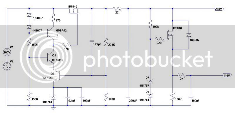
The mosfet is supposed to fully conduct current from drain (pin2) to source (pin3)  when the voltage from gate (pin1) is around  5V or more higher than the source (pin3)

ie. when Vgs > 5V  or so, the resistance thru the series pass mosfet approaches the minimum and current the maximum

That means that when the gate voltage Vg > Vout + 5V  the thing is turned on

Before power on, mosfet Vg and Vs are at 0V of course.

At power on, mosfet Vdrain is the first thing that hits full B+ voltage.

The power up sequence (I think) is firstly D5,D6 -> R3, R2 -> 100V zener

Around the same time, Q1 collector voltage begins to rise > 0, turned on as it is by D5, D6 voltage drops.

So, there begins some Vg on the mosfet, which gets to 5V greater than the Vsource, which starts it conducting leading to mosfet Vs ramping up.

Both the Q1collector and mosfet Vg ramp up, higher than Vs and the ramp of all three continues in step.

When the Vs at the mosfet exceeds the 100V zener voltage, resevoir cap C6 starts to charge up and hold voltage, as well as Q3 turns on which means Q2 can conduct and the whole the 'regulation part' starts rolling.

ie. Q1, Q2, Q3 are sampling the voltage at the mosfet source Vs (via R5/R6 divider) and comparing to a reference voltage in order to adjust the Q1 collector/mosfet Vg voltage. mosfet source Vs follows (5V less) , thereby regulating the Vout.

D8 is a protection diode to prevent conduction across source-drain. There should probably  be a zener across the first mosfet g-s similar to the second one to prevent the voltage from getting too high.

--

In Matta's case, even when we modified things to ensure Q3 turn on, the output voltage seems to ramp up but falter at 140V or so under a very modest load, even though it is much higher at no load.

That suggests that even a tiny load is enough to cause major 'drooping' of the Vout.

That could be because the mosfet can't supply even a tiny amount of current
ie. it's not sufficiently turned on because it's Vgs is not sufficiently near the required 5V

OR

The mosfet gate voltage Vg is only making it to 145V or so, meaning it can supply current but only at a voltage 5V less than the gate  ie. Q1 collector voltage only makes it to 145V under load.

I'm not sure which - would need to measure mosfet gate and source voltages under load again  to know 'how turned on' the mosfet is.

If the mosfet IS turned on, then the problem is with the developed Q1 collector voltage being plain too low.
If the mosfet IS NOT turned on, why not? It is likely borked.

Now I've never been sure what sets the Q1 collector voltage  ie. is it Q1 Vce doing it, biased as it is here, it or is it the mosfet gate somehow setting it?

It's far closer to to Q2's emitter voltage (set by R2/R3 divider) than it's own emitter voltage (set by B+), so ....

In any case, it seems to suggest that Q1, Q2 are NFG if Q1 Vce is that low.

------

Conclusion - could be any/all of Q1,2,3 and even mosfet Q4 that are nfg.

I am pretty sure D5,D6 are OK. R1, R8 are certainly OK and I'm pretty sure R5 is OK.

FIX : verify the working components above and change ALL the &**&&$## components.

-----

The business with the R6-R7 voltage being too low to turn on Q3 is due to the lack of voltage at mosfet Q4 source.
This happens even at no load, let alone with tiny load (leading to major droopage)

It seemed that mosfet Vs ramped up to 216V or so then choked up - perhaps it was throttled back by Vgs dropping less than 5V and the ramped voltage just drained away. Why the throttle back?

Again - could be a borked mosfet or Q1 throttling back, hobbling it to that sad and pitiful voltage.

In any case, we were attempting to force fix a symptom and not the cause of the problem. This issue would affect regulation and not basic ramping to HV. (I think  ::) )

ONE other thing is that the second regulator section could be nfg and 'dragging' the first regulator down.
ie. mosfet 2 goes short circuit and your get 'blow-back' into mosfet1's source. Hmm.....

----

PS - in any case it's not really that important the exact cause - once you have the PSU board out, it's just as easy to replace all Q1,Q2,Q3 and I would say may as well go to IRF840 too at that time.

PPS - I have had ALL of the above components go in one board and the ONLY thing that got me out of the vicious cycle was member 'ppa' mods.

PPPS - there does seem to be a thing whereby if you replace one or two but not all faulty components, the replaced ones die again! That's where replacing ALL the f*^&ckr components AND the 'ppa' fix is the only thing that helps

----

Now, when desoldering the @$%%!& components Q1,2,3, (if you don't have a desolder station), put a 'yanking clip' on the transistor, use lowest heat and put MORE solder on the 3 pins of each to get an even melt at the pins, simultaneous.

Gently, gently yank the sucker out.  Too much heat and you will burn the pads which is a real pain. Too much yank and you will pull the thru-hole vias out. Way-frtized transistor will just crumble :); if so, do each pin yank in turn.
(in fact I almost recommend crushing the thing and doing each pin in turn - better than a poorly executed 3-way yank!)

Once the transistor is out, clean up GENTLY with heat and solder wick (small width). I recommend clean up resulting mess with flux remover.

DO NOT attempt to remove solder first before yanking - you WILL f&** it up.

---

So - anyone else PLEASE feel free to correct this description if you wish  :)  I'm still mystified by the cause-and-effect sequence of operation at power up/down  and failure modes ???  (I am a spice free zone)

Good luck to anyone suffering psu issues here.
 
hi guys!
Im looking for why my unit is not working...
I trimmed the slowstart psu to have 6.4v... when I connect to the unit i measure 5.2v, is it normal?
 
Hi!
when I trim it, the value doesn't change, stays at 5.4V...
I have no sound because of bad edcor xformer 10k:600 sold by a member of this forum... I bought a pm670 kit and 3 of 4 10k:600 don't work after testing. So I ordered 3 xsm from edcor.
I'll tell you
thanx
 
Ah, brings back bad memories. I had 5 out of 8 of my edcores die on me. I think the thin wire on these can't take being shipped.
 
i've found the solder connections on the edcors to be the problem on the  1 that died--showed open circuit, through it in junk box, year later thought to investigate--coil was not o.c., but bad solder joint. maybe a little scraping and ohming is in order
 
pm670.jpg


Here is my unit, enjoy!
Vintage Freed Audio transformers for output for a vintage sound :)

I need some advices:

vu meter: I put a 100k resistor in series with 5k trimmer to adjust tracking: -3dB on vu meter is -3dB level with 1khz sine on position 1(attack)... good idea? I loose aproximately one dB at output...

Tubes: they are not matched... I adjust the unit with RV3 and 5k vu trimmer for stereo matching... good idea? Where can I buy matched 6bc8?

slow start Psu: with no tubes, trimmed to 6.3v, with tubes 5.4V even if I trim up the pot...
Thanx
 
hmm... 100k doesn't really work.
Does someone know how to adjust/modifiy scale tracking on a vu-meter?
It's ok for zero adjustwith 5k trimmer, but the Vu doesn't show real attenuation value: threshold is around 0.5dB per step, and vu is 1/1.5dB per step.
Do you have the problem too?
 
For the GR meter, I used 1K across the meter, but it depends on the meter used.
Mine is still quite jumpy - probably needs something closer to 250ohms or so.

You might try a resistive network instead of just the single resistor across the meter.
BE careful as the there is some 145V there.

Take a look at some other vari-mu circuits to see how resistive networks are applied in order to give a more manageable reading.
 
alexc said:
For the GR meter, I used 1K across the meter, but it depends on the meter used.
Mine is still quite jumpy - probably needs something closer to 250ohms or so.

You might try a resistive network instead of just the single resistor across the meter.
BE careful as the there is some 145V there.

Take a look at some other vari-mu circuits to see how resistive networks are applied in order to give a more manageable reading.

My vu is not jumping, very stable. I tried other resistive networks: another trimmer, 3k6 serial +250trim, +500trim... with more or less success. The problem is still the scale of the vu.Anyway this machine sounds good and I first work with my ears...
I'm gonna write on the panel:
"Why do you apply so much gain reduction? Never mind, man it's not 10dBs, just 3dBs. Enjoy valve's sound!"
 

Latest posts

Back
Top