the Poor Man 660 support thread

GroupDIY Audio Forum

Help Support GroupDIY Audio Forum:

This site may earn a commission from merchant affiliate links, including eBay, Amazon, and others.
Hi

Yep - you're right regarding the +12V - I edited my comment in the previous post.

OK - so regarding the low HV and major drooping under tiny load :

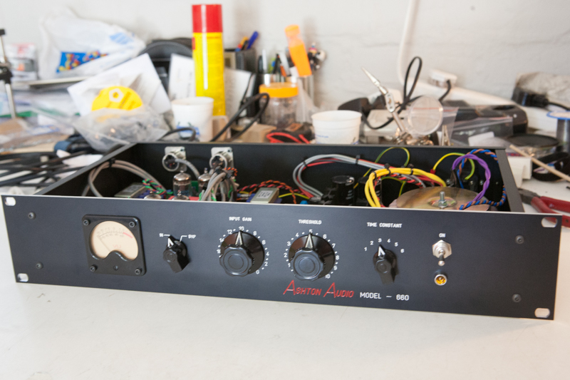
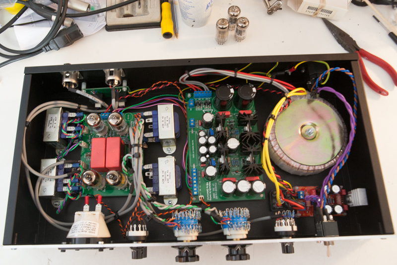
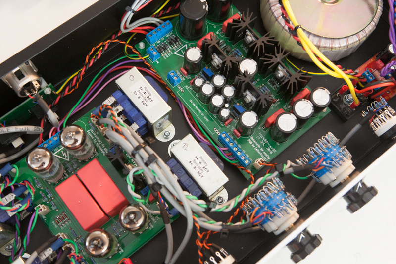
First thing to check is the basic B+ with no load (pull all 6BC8 and 5687)

- you can measure that easily  at the bottom (unbanded) of D6 - this is the first diode below the first big heatsink, nearest the big caps.

That should be around 1.3 your VAC which you said was 265VAC, so around + 350V or so.

ps  - some people have quite a bit higher VAC and so the DC can go up to >+380V)
pps - good time to know the voltage rating of your big caps. I recommend 400V min, 450V better
        (350V is not good!)

To be more thorough, measure that B+ on either side of R1, which is the nearby big 2W resistor.
That's your first B+ dropping resistor.

While you are there, you can confirm you 245V rail again by measuring either side of R8, the other big 2W resistor below the other heast sink.

Those 2W are what burn out when you short the HV for any appreciable time. Big fo-shizzle.
I like to mount them a little off the board so as not to burn the pcb in the event of disaster.

Finally, confirm your 136V rail at the connector again.

So that tells us that your basic B+ is in order and not sapping off anywhere .. untoward ..

Next up, digging about the .. dreaded ... 'valley of broken dreams'

Cheers
 
Hi Alex,

Thanks for the test points!

First up, the cap ratings.

C1+C3 = 400V
C6 = 350V
C5/C7/C9 = 350V
C2/C4/C8/C10 = 630V (Wima Polys)

Voltage on unbanded side of D6 = 366VDC, which looks good.

Either side of R1 = 364VDC
Either side of R8 = 221VDC

The 221VDC on either side of R8 correlates to the voltage at the 245V PCB header, the 136V header reads 117.9VDC.

Hope that helps point us in the right direction!

Cheers

Matt
 
Yep all thats fine - caps all good, no unknown hv current leaking away.

Now to enter 'the valley of shadow ' ...

So, looking now at the first regulator section :

First up, take a look at the top (banded) of the reference zener diode D7 (1N4764)
The zener is at the far end below the second heatsink.

Should be at it's rated voltage of 100V give or take a volt or two.

You can also look both sides of R3 which is just below the 3 little F**ckr transistors.

While you're there, also both sides of R2, above said transistors.

I've fried R2 and R3 on an occasion :)
They provide a current path for the zener and reservoir C5 and get the ball rolling.'

Assuming you have zener lift off, then moving on to the Q3 transistor - measure top of R6 which is the vertical resistor at end of mth*fkr transistor line. (bottom is ground). That should be 0.6V more or less higher than the zener. If not Q3 is likely NFG.

If you are still going, then we look at the Q1, Q2 combo.


D7 banded side looks good sitting at 101VDC

R3 on the C2 side is 363VDC, on the C6 side it drops 221VDC
R2 on the C2 side is 221VDC, on the C6 side it drops 101VDC

Dashing out quickly and will take the Q3-Q1 measurements on my return, just thought I'd post these in the meantime.

Cheers

Matt
 
Ok, just check Q3 at the top of R6, it's sitting at 93VDC, so well below the expected 0.6V drop from the Zener which is sitting at 101VDC, bad Q3?

Any chance the others were damaged as well?

Cheers

Matt
 
OK - zener has current which is good.

The top of R3 is suspect - it should sit 2V or so below bottom of R1, which you said was 366V.
No t neccessary here to check the top (banded) of D6 - should be 1V or so less than 366V.

I think D5 and/or D6 are fritzed gone open circuit. Prepare to  change them both. (I've had this too!)


Nothing else matters till you have D6, D5 working  (and R3, R2 - which appear to be OK).

This looks like you will end up replacing D5, D6 and probably Q1, Q2, Q3 as well.
If you are lucky, R1 and R8 will be intact :)

The well known 'pm660 psu hell'.

But we will see  :mad:

Measure R4 - one side will be at 366V the other should be 1V more than top of R3, which you said was 336V.  If so that means Q1 should be OK too. But maybe (often!) not.

Measure both sides of R5 while you are there :)

 
Hi Alex,

By bad, sorry I saw what I wrote above, it wasn't 336VDC, but rather 363VDC!!! I switched the last two numbers around, so yes it was 364VDC at R1 and then that dropped to 363VDC at R3, so a 1V drop as you anticipated.

I checked the banded side at D6 and am getting 359VDC.

R5 is sitting at 218VDC on C4 side and 219VDC on C6 side.

Hope that helps with further direction!

Matt
 
Cool - top of R3 at B+ less 1.2V or so (=363V) means D5, D6 are OK and so is that branch to the zener.

Now looking at the next branch :

R5 with 1V across it is about right and that means that Q1 is likely OK too.

So next is measure bottom of R4 - should be something like 365V (B+ less 0.6V) or so

--

Now you said the top of R6 is at 93V, and not 0.6V more than the zener (100V or so) - yes, that means Q3 and/or Q2 is borked

The hard bit is to measure the junction of Q2 emitter (pin3) and Q3 collector (pin1) - not easily accessible.
We want (would like) the Q2 emitter (pin3) to be 0.6V less than its' base ie. the junction of R2/R3 (you said 221V).

However it's just as easy/hard to replace both if one of them in known nfg - so :

- you would need to replace Q2, Q3
- check again all  we've been thru, with no load

- if that's figures better re top of R6 then ......

-> now you should have your +245V HV rail in  good order  :) 

I would say it will be some less than spec with your relatively low B+, but regulating at say +230V or so.
That would mean some +122V on the other rail.

But - we'll see.

----

Next would be much simpler HV +136V section checks - issues mostly are related to the much disliked Q1,2,3 'triumvirate of pain'    :'(
 
Thanks Alex,

I measured R4 and get 366VDC, so a volt above your speculative 365VDC.

Trying to source replacement MPSA42's to swap out Q2+Q3, so a standstill till then.

Out of interest, it seems from your summation that this is a common supply issue, what causes it? If it is known problem are the measures I can take to prevent Q2 or Q3 from being damaged down the line?

Cheers

Matt
 
Now we get to areas where it all goes black for me ... I've not gone to the next level of analysis.
Nor do I want to.

Members like 'ppa' would have better answers as to what's going on in reality and what protection is required.

He's written about it and has made improvements, including one more zener to prevent a major fault mechanism.
(around mosfet 1, as is done at mosfet 2).

I know one of my units was a real crapper - until I did his mods and it came back to life and no further issues.
The other 3 of 4 - no issues.

I do think a good many of the psu cases are more related to construction than not, HOWEVER :

I also know that many others' comments regarding the PSU implementation, particularly Kingstons', are certainly valid - this psu is a bit too complicated. Can be simplified with a major improvement in reliability.

For example, 'Guavatone' has a similar HV regulator in his 'orange86' - simple, rock solid, even a complete tool could have it working forever!  I love it, for sure!

Don't have much else to say really - this project is fine in a lot of respects, but if you are having psu issues, it's pretty unhappy a situation. I'm not defending the  psu as implemented, but I have had to learn to live with it.

In my case, maybe I've been relatively lucky - certainly I'm not in a position to redesign it, so I simply carry 'spares'.
But generally, I have been lucky in EE - I charged exorbitant rates in my day based on the ability to 'make systems work' while I was around :)

So - your 'mileage may vary' - sorry not trying to be unkind. Ask the same question in Kingston's 'redesign' thread and I'm sure he will give you an education.

 
Totally, I understand, I have a limited knowledge of theoretical electronics, but a fair share of hands on work, and as with anything one gets better with practice and troubleshooting like this, while at times frustrating, is a great way to work through things in a methodical way to root out issues.

I've seen this thread get a little bitter at times, but as you shared, one accepts this project for what it is, rather than what it isn't.

I chose to not flog the boards and part as many did and am determined to get a stock PM660 up and running and embrace it for what it is.

I'm grateful for the work Analag did in sharing the design, he could have kept it to himself, but didn't, so much respect for that.

Thanks again for all your help and support in this, again, MUCH appreciated!

Cheers

Matt
 
matta said:
Totally, I understand, I have a limited knowledge of theoretical electronics, but a fair share of hands on work, and as with anything one gets better with practice and troubleshooting like this, while at times frustrating, is a great way to work through things in a methodical way to root out issues.

I've seen this thread get a little bitter at times, but as you shared, one accepts this project for what it is, rather than what it isn't.

I chose to not flog the boards and part as many did and am determined to get a stock PM660 up and running and embrace it for what it is.

I'm grateful for the work Analag did in sharing the design, he could have kept it to himself, but didn't, so much respect for that.

Thanks again for all your help and support in this, again, MUCH appreciated!

Cheers

Matt

Hi Matt,
I just wanted to encourage you to go on with this baby. My unit would have serial number 1, since it was the first unit ever build with analags design and Volkers pcbs. There has been a lot of controversal discussion about this unit, but my prototype just worked fine from the very beginning. There are a lot of options for modification and maybe improvement, but I could only advise you to build it stock first. It sounds great!
regards
Bernd
 
So, to summarise, what you have is :

- generally B+ is a bit low : I'm hoping it doesn't stop the regulating
- voltage at R6 of 93V is too low - Q3 is not conducting
- have not explicitly checked Q2 - it may not be conducting either

Otherwise everything else is about right - I'm hoping there is not a 'chicken-and-egg' thing which means the mosfets aren't sufficiently 'turned on' meaning Q2, Q3 may not be turned on .. etc

Sorry - that's all I got  ::)

 
One more thing :

The R7/R6 divider means R6 voltage gets 0.404x post mosfet1 voltage.

Because you have a lowish B+, and with 219V on the mosfet gate (you measured, no load), you may well end up with a voltage too low on the mosfet drain (215V or so) such that the top of R6 will never get high enough to make Q3 conduct.

Especially since your zener is a little high-ish at 101V.

ie. in  the spec case, B+245 at mosfet drain means 245*0.404 -> 99.9V at R6-R7 junction.
   
    typical 1N4764 is 98Vdc, so the R6-R7 junction voltage is high enough to turn on Q3 and start things .. circulating ..

You may have a sad case of too low B+ and too high a zener voltage  :eek:

Perhaps decreasing the 221K to achieve a divider of 102/215 = 0.4744  ie. 165K or so

150/(150+165) = 0.476* 215V (expected max drain from 221V gate) -> 102V at R6-R7 junction

which exceeds the 101V zener you are seeing and therefore allows Q3 to in fact turn on and complete the chicken-egg !


I do think it is something like that - Q3 is probably OK. It just hasn't had it's day in the sun yet.

When you draw some current, it gets even more turned off and exacerbates the 'turn off'.
That's what I mean about the chicken-and-egg regulation thing.

Maybe some sharper head can help here (HELP!)

 
Thanks bernbrue for your words on encouragement. I'm still encouraged by it and the support Alex has provided, it's nice to know I'm not alone and am grateful for all the support.

This unit is actually for a very close friend, he was a mentor to me in my recording apprenticeship years ago and I wanted to give him something to thank him for both his friendship and support, much like this community has supported me over the years. I think we are all to quick to forget and thank those that have gone before us, taught us, directed us and encouraged us along the way.

On a positive note, while I wait for replacement transistors, I thought I'd post a few pics, maybe as an encouragement for other builders as well.

pm660.jpg


pm660-2.jpg


pm660-3.jpg


Thank you ALL once again for your support and the community at large.

Cheers

Matt
 
Fook yeah! Nice unit boyo

And wait a while - Q3 may not be borked, as I was working on above!
 
alexc said:
Fook yeah! Nice unit boyo

And wait a while - Q3 may not be borked, as I was working on above!

Thanks will do, holding thumbs that someone can confirm your findings and maybe it's as simple as changing some of the resistor values to get those transistors working.

Cheers

Matt

 
ps - at least, reducing a resistor value can be 'prototyped' by adding parallel resistance
      ie. you could test without taking apart by jumpering in some resistance, 680K, onto the 221K
          maybe.

---

Yes - we need a serious guy here to help out and check the numbers.

I can think of few up to the task  :) 

Here's hoping ...
 
Simple : parallel 680K onto the R7 221K resistor to give 166K8 total.  (watch that 104V or so !)

150K/(150K+166K8) * 221V ( your reported B+245V rail)  -> 104.6V

104.6V at the base of Q3 is enough to exceed the 101V you measured at it's emitter (zener voltage)

Worth a shot and shouldn't burn anything up  (DISCLAIMER!!!)

Reviewing the info R4 bottom at 366V appears to have no drop (depending on presicion of readings) and makes me think more so that the Q1,2,3 branch is not conducting - due to Q3 turned off, thus borking mosfet1 bias.

Making me more sure the issue is low B+/high zener.

---

If it works, you shouldn't notice too much, maybe a little rise at the +245V terminal, but it should maintain itself when you put in a light load of 2x6BC8.

Good luck - if you don't get any other help, that's what I would do. However - I could be wrong (been so before ???)

Regards Matta - what great kharma there is in that unit waiting to be gifted :)

Cripes - if you are totally stuck, send me the psu and I'll tech it for you gratis!


Latest posts

Back
Top