Advice b4 i start building my Green Pre's?

GroupDIY Audio Forum

Help Support GroupDIY Audio Forum:

This site may earn a commission from merchant affiliate links, including eBay, Amazon, and others.

jaotao

Active member
Joined
Jun 22, 2004
Messages
37
Location
London UK
Hello all i'm finally getting around to building my Green Pres (first DIY proj) and was wondering if anyone's got any advice about what to expect, what to start with first, what to do, what not to do, etc etc?

I've been soldering cables for a few years and i've got an electronicsy mate who'll be helping and overseeing my work but other than that my plan is basically to follow what i see on Peter's photos, carefully checking and learning about each of Ptown's kit's component as i go, is this utterly naive? (finding it hard to work out another approach)

I've got a stardard multi-meter and soldering iron, a nice clean work space, lots of patience. 4 pcb's + psu, components for 2 channels.

Any thoughts at all are greatly appreciated. Thanks in advance.

Matt
 
Or you could check the advice given to you the first time you started this thread.

http://www.groupdiy.com/index.php?topic=14875

Matt
 
Patience.

Good thing that, build slowly & check things as you go. Measure each resistor as you put it in, on the 1% resistor parts Orange & Red can sometimes look very similar.

Peter
 
Familiarize yourself with the different components before starting. Otherwise you're bound to make mistakes.

Read the Green Pre Meta and use the search function. All the information you will need is already here.

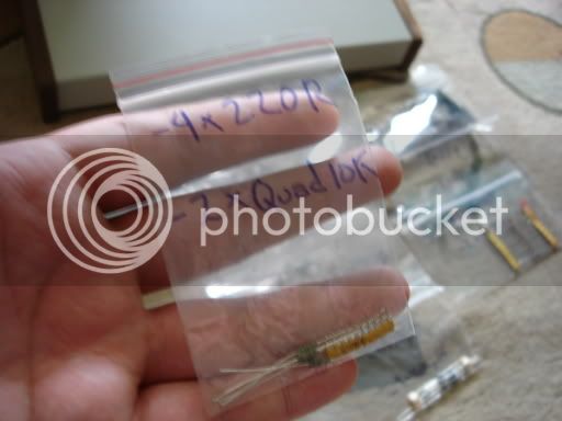
When I stuff PCBs, I like to bag and mark all the parts before I start, like this:

DSC00041.jpg


It really makes stuffing the board easier.

Double- and triple-check to make sure you're soldering the right component in the right place.

And don't forget to read the Green Pre Meta.

Let me say that again: READ THE META.

Peace,
Al.
 
Thanks people. Sorry Fucanay i thought i didn't submit my last post (i've been working myself to death lately!!! And remember sitting there like a zombie thinking "na, post later") - good advice. Yeah i'm pretty feeling confident now... ha! : )

thanks again
 
Look around for these files:
Green_Schematic_V14.pdf
Green_Schematic_Meter_V14.pdf
green_pre.pdf

The ones Peter includes are not quite accurate.


Also, have a look for my threads on the Green as there's a few interesting things to note.

But above all, take your time and don't freak out! :grin:
 
i would advise getting all of your parts at one time. i assembled my pre boards, and then sat on them for months waiting to order PSU parts / chassis.
all that waiting made me lose momentum on the project making it hard to get motivated to work on it.

i am finally getting around to the PSU stuff. hopefully will be done soon.
 
[quote author="DaxLiniere"]Look around for these files:
Green_Schematic_V14.pdf
Green_Schematic_Meter_V14.pdf
green_pre.pdf

The ones Peter includes are not quite accurate.


[/quote]
:shock:

peter c.'s schematics are accurate from what i can tell. i used them to reference the circuit when building. all of the information is there, you just have to have patience (as peter c. stated). peter c.'s overlay may look a little cramped, but that's how all of peter c.'s overlays look. :wink:
the files you are referring to are frank's (nrgrecording) i believe.
one thing i've learned is that many times you can look at a schematic and actually find the answer to your question by using some simple reasoning.
remember, in the past people didn't have overlays, they just had schems.
do yourself a favor and keep looking over the schematics and things become interesting and a better understanding begins to bloom.
oh yeah, did i mention always check your resistors with an ohm meter and try to get the values as close as possible, especially if you are planning to have more than one channel in the same box). i built my 2 channels side by side to keep things the same on both.
regards,
grant
 
Did someone say confused? What is my name again... oh hell, it is all YOUR fault Pete! Hah hah!

I've built probably around 8 different Greens, from Pete's REV1 to the current REV14 and all turned out fine using his docs... expect for the large explosion. just kidding... all went VERY smoothly.

Happy building Matt!

Cheers

Matt
 
[quote author="DaxLiniere"]Look around for these files: Green_Schematic_V14.pdf Green_Schematic_Meter_V14.pdf[/quote]
Those are schematics I drew from the actual pcb. Here are the differences I found between the original schematic and the pcb:

On the pcb, the "-" side of the 4700uf is coming from the upper 22uF cap instead of the "+" side coming from lower one as shown on the schematic;

The main schematic doesn't show the .1uFs in parallel with the electrolytic audio coupling caps;

The main schematic doesn't show the 10 ohm resistors and the 47uF decoupling cap on pins 4 and 8 of the 5532s;

The main schematic doesn't show the 100K to ground on the "out" side of the HP switch;

The main schematic shows TL072s, and LM833s for opamps, but the board shows 5532s;

The main schematic shows 10pFs in parallel with the FB resistors of the output opamps, but the board shows 22pFs;

The main schematic doesn't show the phase switch.

The meter schematic gives 10K for the input resistor, but the pcb shows 22K;

The meter schematic doesn't show the .1uF after the first opamp;

The meter schematic shows a 10ohm and .1uF in series from R19 to -17V that does not exist on the pcb.

The meter schematic doesn't show the 10ohm/10uF network between the +/- supply rails and +/-V pins of the TL074s and the LM339;

The meter schematic doesn't show the 220ohm between the 914 anode and the 560 emitter like is on the pcb

That's all I found. Keep in mind that you can easily build it using Peter's assembly pictures and going by the values on the pcb without even using the schematic. I'm just anal (already mentioned that once :wink:) and once I found it didn't match the pcb, I had to draw it out correctly. Also, keep in mind there could still be a mistake on my schematics. Peter found a few to start with, but I think we beat them out pretty good.
 
Peter,
You are more than welcome to use my schematics however you wish. I can also edit them for you if you want something changed. I did them in RIMU and can even send you those files if you have that schematic/pcb program.
 

Latest posts

Back
Top