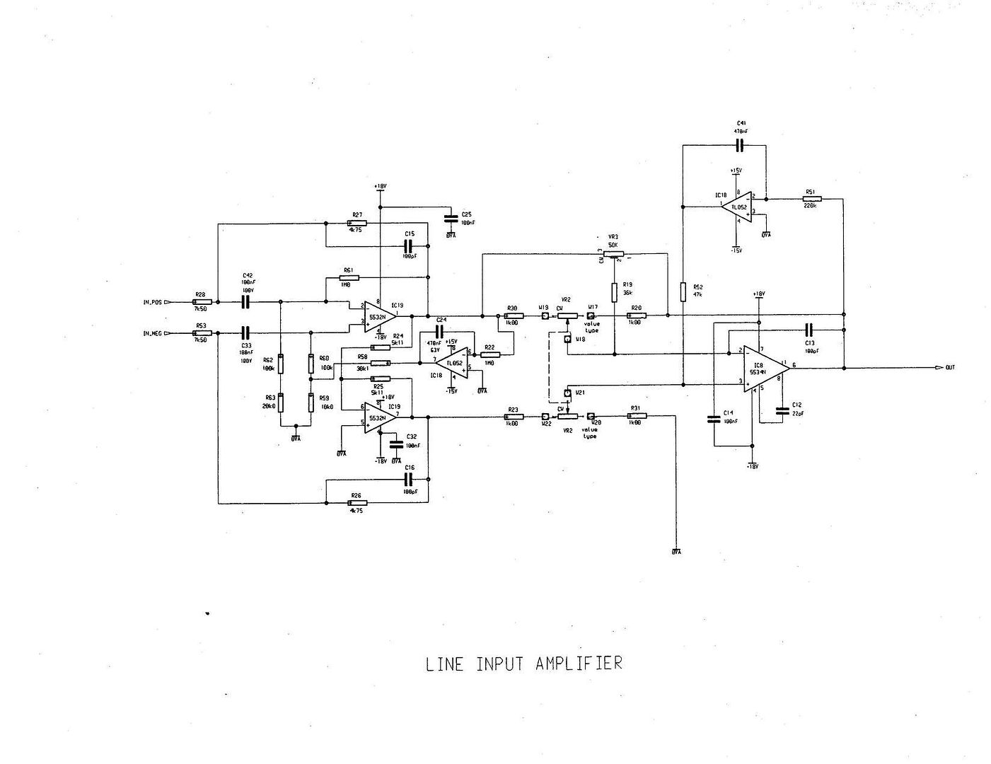
9000 XL line amp schemo here

GroupDIY Audio Forum

Help Support GroupDIY Audio Forum:

This site may earn a commission from merchant affiliate links, including eBay, Amazon, and others.

pucho812

Well-known member
Joined
Oct 4, 2004
Messages
14,949
Location
third stone from the sun
discuss

LineInputAmplifier9000.jpg
 
A few things I don't quite understand:

What is the second (lower) half of the first NE5532 (IC19)doing?

R27 and R61 - these aren't quite in parallel, but why do we have both in the feedback path. Is R27 + C15 just a low-pass filter? I can't read the actual values of them....

IC8 is looking at the difference between the outputs from each half of the NE5532 (IC19) at the beginning, but I can't see what the purpose is here.

Finally, I'm generally confused about the use of R59, R60, R62 and R63 (near the input).
 
thanks Pucho...

been looking for this one for quite some time.
it's not exactly the simplest line amp i've ever seen!
anybody know the value of the dual pot VR2?

cheers... Mark.

ps. don't suppose you have the mix amp schem lying around the place too?
 
What is the second (lower) half of the first NE5532 (IC19)doing?

is it not some sort of inverting voltage follower with feedback?

IC8 is looking at the difference between the outputs from each half of the NE5532 (IC19) at the beginning, but I can't see what the purpose is here.

isn't it to deballance the signal and provide CMRR?

it looks a bit like a ballanced in - ballanced out superbal with a differential amp afterwards to deballance and DC servos on the chips that count.
 
Thanks :thumb:
Right now I'm not smart enough to discuss but one day it will come in handy (one day when I'm building a summing mixer or so :shock: )
 
[quote author="rodabod"]A few things I don't quite understand:
What is the second (lower) half of the first NE5532 (IC19)doing?
[/quote]

The second 5532 is an inverter and at the output produce a signal identical to the one at the output of the first 5532 but inverted.
So you can look at the two 5532s and R27, R28, R53,R26 as it would be a balanced high Z input, balanced low Z output buffer, that feeds IC8.

[quote author="rodabod"]
IC8 is looking at the difference between the outputs from each half of the NE5532 (IC19) at the beginning, but I can't see what the purpose is here.
[/quote]

Yes, IC8 looks at the difference between the two outs and the GAIN is depending on the position of pots.
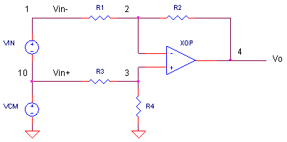
You can simplify the schematic of IC8, plus resistors, plus pots to this:


image4.gif


Vout=(V1-V2)X R2/R1
where V1 is voltage at out of first 5532, V2 is voltage at out of the second 5532, and R2 should be equal to R4, and R1 should be equal to R3.
When pots are in mid position R1=R2=R3=R4 and Vout=V1-V2 (unity gain).
You can amplify or attenuate depending on the pots position.

[quote author="rodabod"]Finally, I'm generally confused about the use of R59, R60, R62 and R63 (near the input).[/quote]

The two TL052s have DC servo function. The first TL052 watch the DC at the output of the first 5532 and injects a correction voltage to the noninverting input. R62,R63,R59,R68 will help this without debalancing the input Z.
The second TL052 is also a DC servo, and monitors the DC at IC8 out, and injects correction voltage to noninverting in of IC8

chrissugar
 
Ahh, ok. I didn't realise that the second half of the NE5532 was an inverter! Now I see why it is unbalanced at the final stage, etc.

Thanks,

Roddy
 
When pots are in mid position R1=R2=R3=R4 and Vout=V1-V2 (unity gain).

does that mean that any linear pot can be used for VR2 but the size will determine the boost/attenuate range? 2k giving 12dB boost or cut?

cheers.
 
[quote author="Mlewis"]does that mean that any linear pot can be used for VR2 but the size will determine the boost/attenuate range? 2k giving 12dB boost or cut?
[/quote]

Yes, the value of the pot will determine the boost/attenuate range.
Although a 2k pot will not give you 12dB boost/cut. You have to add the values of the resistors. For 12dB you need to have R2/R1=4 and that is possible if pot is 3k (odd value).
-1k pot will boost 6dB
-5K pot will boost ~15dB
-10k pot will boost ~20dB

chrissugar

LATER EDIT - Corrected the dB values because I made a mistake.
 
[quote author="chrissugar"]Do you have more? :grin:

chrissugar[/quote]

I might :green: acutally I do but the schemo pages are 2 big for the scanner so trying to work out the best way to chop them up. That just happened to fit on regular size paper. so it got scanned. the eq's are unreal. I am still tryint to get my head around the constant bandwith setting of the E button. :thumb:
 
awesome. I really like their designs, so easy and clean it hurts.

The impedence balanced gain setup is simply elegant. I never thought of it before but after seeing it, it strikes me as how necessary it is.

3 opamps and a handful of resistors and a pair of caps. couldn't be more easy.

Please post more!
 
[quote author="keefaz"]As VR2 manages the gain, shouldn't it be a dual log pot rather than a dual lin pot ?[/quote]

I don't think it would be a good idea. There are two reasons for this.

1-Dual log or antilog pots do not track equally so the conditions R2=R4 and R1=R3 would not be satisfied
2-because this circuit produce identical values of boost and attenuation it is logical to have the same feel/distribution for either sides of 0dB.
For example for -10dB to 0dB to +10dB situation, it would be strange to have -10dB to 0dB ocupy a quater of the pot cursor and three fourth the 0dB to +10dB range.

chrissugar
 
Pucho, please post some more. If I understand it right the EQ can be separated into two separate circuits, so if you decide you want to build only one of them you don't need anymore those unobtainable multigang pots.

Come on Pucho, let me help you. :green:

chrissugar
 

Latest posts

Back
Top