[quote author="rodabod"]A few things I don't quite understand:
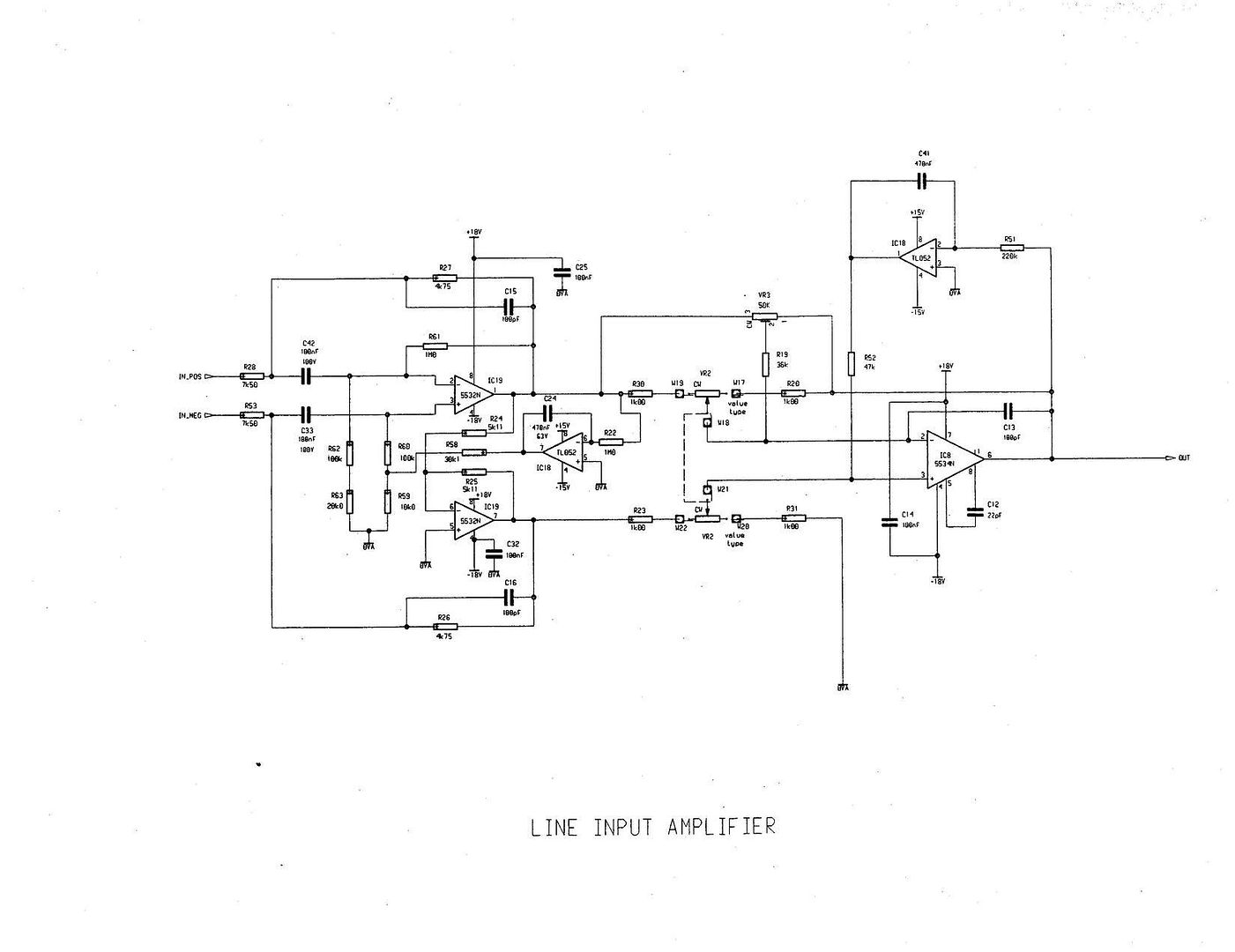
What is the second (lower) half of the first NE5532 (IC19)doing?
[/quote]
The second 5532 is an inverter and at the output produce a signal identical to the one at the output of the first 5532 but inverted.
So you can look at the two 5532s and R27, R28, R53,R26 as it would be a balanced high Z input, balanced low Z output buffer, that feeds IC8.
[quote author="rodabod"]
IC8 is looking at the difference between the outputs from each half of the NE5532 (IC19) at the beginning, but I can't see what the purpose is here.
[/quote]
Yes, IC8 looks at the difference between the two outs and the GAIN is depending on the position of pots.
You can simplify the schematic of IC8, plus resistors, plus pots to this:
Vout=(V1-V2)X R2/R1
where V1 is voltage at out of first 5532, V2 is voltage at out of the second 5532, and R2 should be equal to R4, and R1 should be equal to R3.
When pots are in mid position R1=R2=R3=R4 and Vout=V1-V2 (unity gain).
You can amplify or attenuate depending on the pots position.
[quote author="rodabod"]Finally, I'm generally confused about the use of R59, R60, R62 and R63 (near the input).[/quote]
The two TL052s have DC servo function. The first TL052 watch the DC at the output of the first 5532 and injects a correction voltage to the noninverting input. R62,R63,R59,R68 will help this without debalancing the input Z.
The second TL052 is also a DC servo, and monitors the DC at IC8 out, and injects correction voltage to noninverting in of IC8
chrissugar


")