transistors and gain

GroupDIY Audio Forum

Help Support GroupDIY Audio Forum:

This site may earn a commission from merchant affiliate links, including eBay, Amazon, and others.

Sleeper

Well-known member
Joined
Jun 6, 2004
Messages
649
Location
Los Angeles
Hi there.
I've been reading and studying app notes and pdf's galore and I'm still not getting how this works.

What i need to do is get a little more gain out of this fuzz circuit from an acoustic 360 bass amp. When it's switched IN and the attack and gain are maxed out I'm getting volume drop compared to when the circuit is bypassed. how do I get higher output levels from this?
normal_360_fuzz.gif


my 2n1306 is vintage and obsolete so I can't get one with a higher hfe. I don't want to change it... the fuzz is very good sounding.

Oh, duh. I just spotted something. there's a voltage divider on the input. maybe changing the 22k 100k ratio on the input might do it.


Still, that's not what I was initially asking about.
I'm looking to squeeze enough level out of this that the level control is useful.

Is there a way to get more gain from transistors, in a circuit like this or is gain just based on hfe and making sure that the things are biased correctly so that the gain available is optimized for minimum (or in this case maximum) distortion.
Is this like an opamp where the 680k and 470k on q1 or the 1m on q3
are part of a feedback network like with an opamp?
I was reading about the darlington pair. maybe this would work...
as you can see, I know just enough to be dangerous, not really enough to address my problem.
Hope someone can push me in the right direction.
Kelly
 
The fuzz effect already has tons of gain, it not a gain issue but output level, it basically takes the audio signal and turns it to square waves. With fuzz engaged your quiet parts ger louder but loud parts get clipped off to level of square wave..

You could probably change the amplitude of the squared off signal with a few resistor values but it "could" change the tone of the sound. If adventurous try reducing the value of 100k between +supply and .1uf cap to gnd. This will increase voltage 47k pulls up to when 1306 switched off.

The last transistor stage is a simple follower so you could perhaps make a 2 transistor gain stage there. This will be a little more difficult but won't affect tone..

JR
 
Hi John, I'm starting to see some light here.
darlingt.gif

this looks interesting.
If i were to pop a darlington pair in place of q3... wait that gives additional current not gain.
http://hyperphysics.phy-astr.gsu.edu/hbase/electronic/npnce3.html#c1
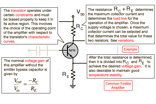
npnce13.gif


ok this is making sense, oh wait. the output is coming off of the emmiter, not the collector.

sheeesh.
I'm in the dark again, wait, that was just a rolling brownout.
I'll keep looking.
feel free to push me along.
Thanks
Kelly
 
Indeed, the darlinton will not give you a larger voltage swing, it just double buffers the emitter follower for higher current gain.
-----

The fuzz circuit is a little difficult to analayze as it isn't designly to cleanly pass signal, but to severely distort it with too much gain. While the 3rd transistor is a clean follower, the first two are configured for high gain and in series. Messing too much with the values around them will alter the frequency response of that gain and the sonic character.

My suggestion to experiment with reducing a resistor value (100k) is intended to increase the the effective max output voltage of the second stage transistor. I suspect you might be able to get a few dB more level without disrupting the circuit too much.

I am not familiar with the 2n1306 so I guess you need to check it's collector breakdown voltage and not exceed that.

JR
 
Did you build this(check for wiring errors first) or is it in a real 360 head that you are not getting volume?

Circuit is like an old school two transistor fuzz like a fuzzrite or EH axis or foxy lady or a number of Japanese effects but designed for 24volts not 9volts with a EF after it like noted above.

First transistor has gain and is inverting out
Second transistor has gain and is inverting out
the pot connected to the collectors via the caps is a crude mix control it mixes the increased by gain signals together
if you set it right you can get a octave maxed the stages add
There are more things going on like the 500K pot kind of working as a feedback R to the base of Q2 and the 22k collector R of the first transistor


problems with it grounded emitters and the bias networks if you built this measure your collector voltages ref to ground.

With a fuzzrite type built with Sis I like the collectors at 2.5V with a 9V supply.
 
Hi Gus and John,
Gus, yeah I built it. the fuzz is really good sounding.

it's the relationship of the fuzzed signal to the not fuzzed when you hit the footswitch. fuzz is just too low.

I'd like to be able to have something approximating unity gain when the fuzz gain pot is at 7 of 10... maybe even a little boost with the fuzz at 10 of 10.

right now I'd get unity gain if I had a 12 of 10...

so to answer John, I think I ought to either raise my input a tad or else try and boost that third stage a bit.

I'd still like to find that typology. it sure does look like the 1M and the 10K should do something with the gain of that stage.

I'll have to bust out the iron tomorrow. Try some things...


Kelly
 
The third stage is an emitter follower (unity gain) - you're not gonna get any more gain out of it.

Does the attack pot affect the gain? I'm just a newbie designer, but it seems to me like it's forming a voltage divider with the gain pot. If you scaled the gain pot up to a 1Meg pot or something, it seems like there ought to be less loss due to the divider formed with the attack pot. Don't know if it would be enough. And it wouldn't make any difference when the attack pot was at either extreme of its travel.

But the first thing you ought to try would be John's suggestion. Changing that resistor should let the signal swing higher, = mo' level (but would it be as clipped?)
 
[quote author="Sleeper"]I'd still like to find that typology. it sure does look like the 1M and the 10K should do something with the gain of that stage. [/quote]

Well... not voltage gain, because there is none. But your instinct to change the topology to another type of follower was right on, try a CFP (Sziklai) follower, which can be configured to have voltage gain. Some explanation from Doug Self here:

http://www.dself.dsl.pipex.com/ampins/discrete/cfp.htm

The 24V rail of your fuzz made me think of the CFP in the Altec 1588B. There's lots of discussion of that circuit in this thread:

http://www.groupdiy.com/index.php?topic=8537

That's the road I would go down, if you really like the quality of the distortion, but simply need higher output. John's suggestion would net more output, though change the character of the distortion. Gus made an important point about the grounded emitters. In my experience that's a limiting factor in a fuzz. Check out Gus's three transistor fuzz, aka The Rocket, distortion for some great ideas on biasing BJT distortion stages.
 
[quote author="JohnRoberts"]
I am not familiar with the 2n1306 so I guess you need to check it's collector breakdown voltage and not exceed that.

JR[/quote]

The 2N1306 is an ancient germanium device; 25V Vcb.
 
[quote author="Sleeper"]Oh, duh. I just spotted something. there's a voltage divider on the input. maybe changing the 22k 100k ratio on the input might do it.[/quote]

I did the math on that. Jumper the 22k and gain 1.7 dBs. My guess is that will make the first gain stage slightly distort worse, and not increase your output for the reasons John mentioned.
 
Hi again and thanks to everybody for the input.
John, I get what you mean about the input. now.
I think, like a lot of problems, one needs some external input in order to rethink it.
like Skipwave said, that input will just change the character of the distortion...
I also realized that I was trying to solve this by working with the existing board. On second or third thought, why do that, the signal goes off board right where I need some boost anyway.
I'll check out the dself article and if thats not the right thing I've already come across plenty of simple booster circuits.
Why not just add a booster after the effect with a trimpot for gain and set it exactly where I want the gain to be. Problem solved. case closed. :grin:
Thanks a million.
Kelly
 
being in the Drawing Board I did not post an answer. I did leave some hints as to what to look for.

Attack is a crude mix control.

When attack at max the output goes down? If I understand your post . That is a hint

Like John posted input level is not a place I would look first

Voltages at the collectors(hint) and other nodes might help you

plus you did not post the schematic you built did you change anything.

google some of the old effect circuits.

redraw the circuit and look at what is happening. Big hint redraw with attack at min , center and max

EDIT look for the 2 knob guild foxey lady google can be your friend
http://fuzzcentral.ssguitar.com/schematics.php

Note the bias setup. HINT
 
Hmmm, yeah, that Attack pot is weird. Crudely mixing two out of phase signals. Wacky. I can see how it would emphasize part of the signal depending on how much phase shift the second bjt introduces.
 
hey gus,skip and all.
for your edification.
I built the moosapotamus version of the 360.
but used the original inductor based eq. Thunder.
http://www.lynx.bc.ca/~jc/360+schm.gif
http://www.lynx.bc.ca/~jc/charlieDpdt.gif

skip-what you say about the out of phase mixing of the signals is correct to my ears. the attack lets you add or emphasize the amount of bass tone you hear. it's not totally linear, you can find sweet spots in the pot travel where the bass is more present than others.... mostly at the bottom edge though.

Gu$. I built it exactly as drawn.(except for the reed switch)
dpdt switch takes the fuzz completely out of the circuit when switched off.
This is where I'm getting gain "jump"/differential. In circuit, with controls set for maximum fuzzed signal loudness is (by ear at this point) about 4db down.

I still have it racked up right now and I'm looking at the sziklai follower.
sh.. I don't have negative voltage.

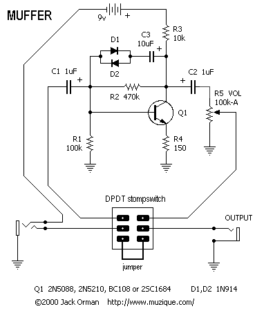
Ok now I'm looking at some boost circuits like this one.
this is what I'm after.
d1 d2 and c3 out, because I don't need more distortion.
I've got to figure out how to deal with with the 25 volt supply.
Trial and error method. I could build it and use a 9volt supply and
measure voltages all around. then change r3 to get the same emitter voltage with the 25volt supply.

OR
should I just be looking for a particular voltage ratio between the base
and collector. and maybe r4 needs to change?
hmmm there's a formula for this right. I'll keep looking and learning.
maybe I should go back to the first post. I think it's there.
scribble scribble/datasheets/calculator etc....
muff.gif
 
[quote author="Sleeper"].....I've got to figure out how to deal with with the 25 volt supply.
Trial and error method. I could build it and use a 9volt supply and
measure voltages all around. then change r3 to get the same emitter voltage with the 25volt supply.[/quote]

Is the problem that you are you planning to put it in a stomp-box? You could use a simple DC-DC charge pump tripler to step a single 9v battery to 25v... it would actually be 27v - diode drop, so around what you want.

Here is a simple topology:
http://www.geofex.com/circuits/+9_to_33.htm

Or if you have an old CMOS chip if you have any lying around, you can use it as an oscillator/charge pump. I used that a couple times... don't know which notebook I sketched out the schem in though.
 
I quess you did not understand my hints or John's hints

I have built a 9V Si circuit somewhat like this it has lots of volume

I am guessing the 2nd or 3th transistor is not biased correctly or you have a wrong value resistor or..

So measure the DC voltages ref to ground of all the transistors collectors and bases and emitters. The 2nd gain stage and/or Emitter follower (EF) section might be not in a good part of it operating range.

Post the readings

I am not a fan of the 360 bias setup grounded emitter, even with the feedback from collector to base. That type of bias is too device dependant IMO.

The link to the foxey lady has a more stable bias that allows different Hfe devices.

Check the book the art of electronics for how different bias setups work and what is more repeatable

Measure DC voltage at all the resistor nodes and post them as well
 
I just checked the schematic

http://www.lynx.bc.ca/~jc/acoustic360piazza.gif

Note the nodes marked B

connected to a 2n2926 NPN transistor emitter to node marked B collector to ground. This is maybe using some reverse emitter collector voltage breakdown of that transistor I would guess as a kind of shunt voltage regulator.

How repeatable is the voltage? I noted at http://www.lynx.bc.ca/~jc/pedals360.html
someone measured 8vdc
 
For the beginning,
can you measure please voltages on bases, collectors, emitters of your transistors?
(You should use some voltmter with high imput resistance).
I would use an oscilloscope, a first to check voltages, then to see signals on them, applying a sine wave from a tone generator.
 
Back
Top