Altec 9470A / 9475A rack-up

GroupDIY Audio Forum

Help Support GroupDIY Audio Forum:

This site may earn a commission from merchant affiliate links, including eBay, Amazon, and others.
Hi everyone.

Thank you so much Doug for all the info and help provided

I'm in the process of repairing one my Altec 9475A units, I don't know if it's better to post here (in order to concentrate 9475 relevant info)  of do a separate thread in the Lab. Please let me know what you think is proper.

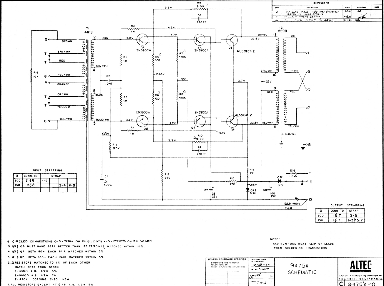
Here is the schematic:

L0yzWyn.png


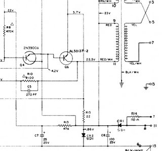
smaller part of the schematic

vwNsoFXm.png


I bought the module already in this condition, and never use it before.

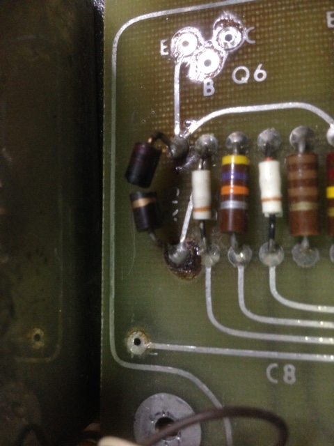
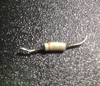
R15 (22r) Resistor burned and it's broken. I can see the melted solder on the resistor's solder pads.


pMOqRQRl.jpg


I suspected something went wrong with the output stage Transistors Q5,Q6, but I removed both transistors and measure them with Peak DC75, and both measure fine.
Transistors are marked on the schematic AL50137-2, but that's probably and internal Altec code, the transistors are marked RCA 35934.
I even  bought 2N2219 replacement transistors just in case, and selected for gain values closer to the originals, but it seems the problem that bruned the resistor might be elsewhere.

I removed the 2 Electrolytic transistors C7 and C8 (they will be binned and replaced) and measured them, none was shorted or open.
Although C7 , 25uf 25V, has a ESR value of 4r that seems a bit high, 2x more than the normal reference ESR values for vintage caps in my tables.

Also CR2 Didode that was next to the resistor on the PCB, seems crooked from the heat,CR1 Diode looks a bit crooked also.
Altec service Manual, lists 1N456 Diode has the replacement.
I measured CR2 and seems to measure ok, 0.6v forward voltage drop, and blocks in the other way around

bItCFSvm.jpg


Tested and measured Q1,Q2,Q3 and Q4, and all transistors are fine

What do you think might have contributed to R15 Burn?

Thank you
 
Another question is regarding replacement of C7 and C8.

The caps are rated at 25V, and the voltage supplied to the module is 24V, caps nowadays are much smaller than in the 60s, so I will replace the caps higher voltage caps like 50V.

Could I also increase the Capacitance value?
like 470uf for C8 and 100uf for C7?

thanks


Outputs are 2N3053 on the 9470 schematic. 

The first two stages were also once 6 pin duals.

Lack of a ground could have burned R15 from RFI.  People frequently miss that chassis and power negative are not connected in the module, and leave chassis disconnected.  I said elsewhere I saw instant 1A current draw like that once, and they came with a hang tag warning about it.

I went through a lot of (24) 9470's once, checking current draw and measuring R15.  Variances in R15 where the entire difference in current draw.

You could increase C78/8 values, though there's not a problem with those values either.  I think I used to usually make both 100. 

I've not ever made sense of the 110Ω optional power input resistor.  I've never seen it wired to that point, and don't recall and notes on it. 
 

Attachments

  • 9475pairPSU_1.jpg
    9475pairPSU_1.jpg
    145.9 KB · Views: 31
EmRR said:
Outputs are 2N3053 on the 9470 schematic.

Thanks, I didn't have the 9470 documents so I didn't know about the 2N3053 being used on the 9470. I have them now.
So the docs for the 9470 have the reference for the output transistors 2N3053, while maintaining an Altec ref for the input transistors.
And the docs for the 9475 have the reference 2N3900A for the input transistors but Altec ref for the output transistors.


EmRR said:
Lack of a ground could have burned R15 from RFI. People frequently miss that chassis and power negative are not connected in the module, and leave chassis disconnected. I said elsewhere I saw instant 1A current draw like that once, and they came with a hang tag warning about it.

Yes, that could be it, maybe someone didn't properly connect one of the grounds.
I will measure all the components in the module to be sure they're ok.
And will try the modules out with all the proper ground connections

EmRR said:
I went through a lot of (24) 9470's once, checking current draw and measuring R15. Variances in R15 where the entire difference in current draw.

I will replace that with a Metal Film 1%, maybe make it 1W ?

EmRR said:
You could increase C78/8 values, though there's not a problem with those values either. I think I used to usually make both 100.

Thanks will do that
Also the 25uf value is not friendly for the present days standard values.

EmRR said:
I've not ever made sense of the 110Ω optional power input resistor. I've never seen it wired to that point, and don't recall and notes on it.

Checking the schematics doesn't seem that if the positive Power is wired to the R14 110r resistor in Point 7 instead of point 11, that the 9475 will not be in high power mode,will be the same as the normal mode on the 9470?

If you connect power to Point 11 bypassing that way the R14 resistor then the 9475 is in High Power mode, the same thing as strapping 5 and 6 on 9470.
At least is what I could understand from analyzing both schematics

Thank you
 
Last edited:
Whoops said:
I will replace that with a Metal Film 1%, maybe make it 1W ?

Also the 25uf value is not friendly for the present days standard values.

Checking the schematics doesn't seem that if the positive Power is wired to the R14 110r resistor in Point 7 instead of point 11, that the 9475 will not be in high power mode,will be the same as the normal mode on the 9470?

If you connect power to Point 11 bypassing that way the R14 resistor then the 9475 is in High Power mode, the same thing as strapping 5 and 6 on 9470.
At least is what I could understand from analyzing both schematics

Thank you


22Ω; you still want it to fuse, right?  That one did and the transistors seem to have survived. 

Make the 25mfd anything you want.  33-100. 

Yes, low power on the 9470, but no mention in the 9475 manual, or the 250T3 console info.  Different circuit boards, so interesting they included it. 

 
EmRR said:
22Ω; you still want it to fuse, right?  That one did and the transistors seem to have survived. 

Yes, you're right. Got it
In reality it would be better to have a fuse there, that way the resistor could be of an higher wattage and not run so hot.

Both boards are brown under the resistor and under the Transistors. These transistors could probably fry an egg in normal operation
 
EmRR said:
Yes, low power on the 9470, but no mention in the 9475 manual, or the 250T3 console info.  Different circuit boards, so interesting they included it.

Yes, I also tried to find any reference to it but didn't see any.

In your experience do you prefer these amps in Normal mode or High Power mode?

 
Thank you so much for the doc rackmonkey.

The matching specs info for the output transistor 2N3053 are an hfe of 125 or higher measure at 50mA of Collector Current (Ic)
(Altec also has that note in the 9475 and 9470 schematics)

index.php


I have 2 transistor testers, the Peak Atlas DCA75 Pro and the Atmega based MK-328.
The MK-328 measures hfe with a fixed base current of 9.2uA and the DCA75 measures at a fixed current but at 5mA, with the curve tracing facility it can go higher, but I thin 12mA is the max.

So if anyone ever needs to replace the output transistor and want to keep them up to Altec specs, then should measure them with Rod Elliot Project 177 circuit. The circuit is for a constant Collector current  hfe measurement and you can build it for 50mA.

Altec only says 125 or higher but Doug said before that he had problems when replacing transistor with higher gain than the originals,  so it seems "125 or higher"  is not totally correct, may more like "125 and higher but not too much higher"

But Doug,  has much more experience in that
 

Attachments

  • Screen Shot 2020-01-27 at 2.53.22 AM.png
    Screen Shot 2020-01-27 at 2.53.22 AM.png
    19.7 KB · Views: 199
EmRR said:
I had a hard time finding transistors under 200 IIRC.

The 2N2219A I bought could be used as replacements also.
Measured HFE with the DCA75 Ic=5mA:

- The original transistors measure between 100 to 115 (measured 4 of them)
- The 2N2219A measure in the 140 range (measured 11 of them)

of course the values are measured with a collector current of 5mA, if the hfe test is at 50mA, all these values will be higher.


Doug were you able to do the hfe measurements at 50mA?
which circuit did you use or recommend?

Thanks
 
Last edited:
Measured all the components in my module, just to be sure everything was fine before powering it up.

there's a typo in the parts list of 9475A Altec documentation,
resistors R9,R10 are 9.1k or 9100r and not 91,000r as listed. The value is presented correctly on the 9475A schematic and also in the 9470 Altec document.

index.php


I replaced resistors R5+R6 and R7+R8, just because I have a lot of those resistors in stock and nowadays it's easier to match them even closer than back in the day. Maybe also the values drifted a bit over the years.

Besides that everything seems fine, next will be powering up and test the module
 

Attachments

  • Screen Shot 2020-01-27 at 19.06.45.png
    Screen Shot 2020-01-27 at 19.06.45.png
    227.9 KB · Views: 117
Last edited:
in order to help out future repairs and troubleshooting,
here is the top of the pcb with the component reference
 

Attachments

  • Altec 9475A PCB components top .png
    Altec 9475A PCB components top .png
    731.2 KB · Views: 54
I just came across a 9470A that has a 2.2M for R11 (normally 220K).  Appears to have been added later and was the only one in a batch of six that had this.  R15 (22r) was toasted pretty bad and the adjacent diode was open.
 
lassoharp said:
I just came across a 9470A that has a 2.2M for R11 (normally 220K).

Probably someone replaced the 220K with the wrong value

lassoharp said:
Appears to have been added later and was the only one in a batch of six that had this.  R15 (22r) was toasted pretty bad and the adjacent diode was open.

I also had R15 toasted but the Diode survived
 
lassoharp said:
R15 (22r) was toasted pretty bad and the adjacent diode was open.

Sounds like a good time to remind there are multiple ground and chassis points that aren't pre-tied, and chassis floating will make there draw something over 1A immediately, probably taking out that stuff and multiple transistors. 
 
Whoops, What was your method for removing the metal shield caps from the Q1-2 and 3-4 pairs?  Mine are jammed on really tight
 
Back
Top