


livingnote
Well-known member
>>>This is one of the old, discontinued Crush-N-Blend threads<<<
For current CnB information go to:
http://groupdiy.com/index.php?topic=61934.0
To keep some order, here's the official support thread for installing the internal crush-n-blend for you guys. I have taken the liberty of adding the instructions from the other thread as I kinda hijacked it myself with that front panel. Post any questions here.
Also, I have the boards in stock if you can't or don't want to etch, for the EU it's 10€ including postage and for international it's 12€. You have to drill'em yourself, but yeah, microseries...If I sell'em out, I'll just do a pro run next time.
Anyway, here goes:
First off, blueprints! Please be fair.
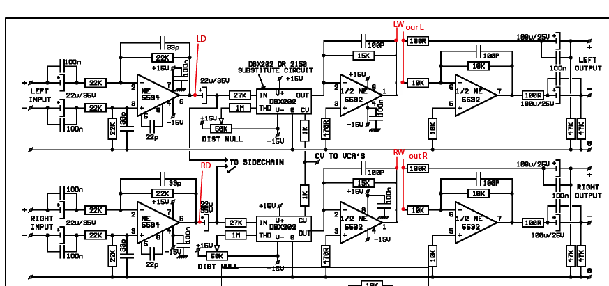
Schematic
Components
Photopositive 1200 dpi
And BOM:
3 x 5532N and their sockets
4 x 39K
12 x 10K
2 x 91K
1 Pot is standard 2x10K
8 x electrolytics 22µ or more
10 x 100n WIMA
6 x 33p or 20p wima
Optional:
4x 22k
2x 470r
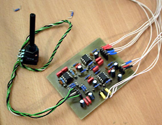
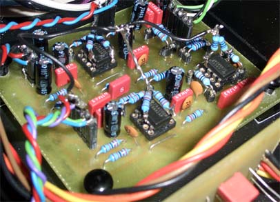
And here the finished build:
Installation procedure:
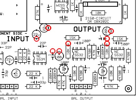
Here's a good explains-it-all pic by creal:
After a bit of thought, I decided it would be best to get in there right before the VCA
input cap, and to go out after the first opamp in the output section.
The idea is to tap off the input, and "break in" to the output. Now there were
some differences on the rev9 board from the rev7 schemo, so we'll be lifting
caps on the output in place of the 100R.
These are the legs we have to lift. It'll be the + side of the input caps, and the
output caps as well as the 10K resistor that goes to the inverting opamp.
In practise, this looks like this:
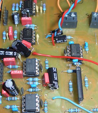
Note that I screwed up a little here, I forgot to lift the output 10K's. Also, I didn't solder
the wire to the input caps' legs, which I corrected (it was 4AM) by soldering a separate wire to the
Cap leg itself and then twisting them together :")
Now for the actual connections (blue is left, red is right):
1. On the input caps, solder the lifted leg to the wire and to the hole where it came
from, retaining the original continuity. Alternatively, you can just solder in a wire on the
bottom of the PCB. All we want to do is sniff the signal, while keeping the artery to the VCA intact.
2. Solder the output caps' freed legs as well as the freed 10K leg all together and attach
a separate wire to them.
Now we have our signal tapping point as well as our little "window" on the output to
break into.
Before we proceed, it is a good idea to twist together the output wires respectively
and see if the compressor still works as before. That way, we'll know if we screwed
up here and it will save a lot of headache.
Now for the actual implant:
It's a good idea to power up the CnB board by itself first before you stick it into your
SSL. That way, if you have anything backwards, you'll just screw up a little part of
things.
Additionally, find a good spot for the CnB board well away from the tranny to make
sure it does not pick up hum. Being unbalanced, it's quite the antenna and so special care
must be taken to ensure it stays quiet. (Yah, screwed that one up myself).
On the Crush board, we have LD and RD (Left Dry and Right Dry), these guys get hooked
up to the wires on the input caps.
Next, we have LW and RW on the CnB input, these go where the wire comes out of the
PCB at the output.
Now for the CnB output: Hook this up to the soldered-together-caps-n-resistor legs.
Then, carefully bring your patient back from his anesthesia and if all went well, you have
yourself a blend control.
Side Note: This has worked great across the board without the bias resistors, but if you wanna adapt to the same as in the SSL, here goes:
Carefully bend up legs 3 and 5, and to each of these, solder a 22K resistor to the two input
opamps' legs each, and for the output one, grab two 470R ones.
Solder the R's other ends together, and hook that point to ground somewhere.
I can't be sure this really makes a difference, but to me it feels as though the construction sounds more "open" with the resistors attached. And then I feel it doesn't again. And then I feel it does. Oh well. You can just leave'em out, I guess...
Alright, show's yours. And be sure to post pictures here if you finish one ;D
For current CnB information go to:
http://groupdiy.com/index.php?topic=61934.0
To keep some order, here's the official support thread for installing the internal crush-n-blend for you guys. I have taken the liberty of adding the instructions from the other thread as I kinda hijacked it myself with that front panel. Post any questions here.
Also, I have the boards in stock if you can't or don't want to etch, for the EU it's 10€ including postage and for international it's 12€. You have to drill'em yourself, but yeah, microseries...If I sell'em out, I'll just do a pro run next time.
Anyway, here goes:
First off, blueprints! Please be fair.
Schematic
Components
Photopositive 1200 dpi
And BOM:
3 x 5532N and their sockets
4 x 39K
12 x 10K
2 x 91K
1 Pot is standard 2x10K
8 x electrolytics 22µ or more
10 x 100n WIMA
6 x 33p or 20p wima
Optional:
4x 22k
2x 470r
And here the finished build:
Installation procedure:
Here's a good explains-it-all pic by creal:
After a bit of thought, I decided it would be best to get in there right before the VCA
input cap, and to go out after the first opamp in the output section.
The idea is to tap off the input, and "break in" to the output. Now there were
some differences on the rev9 board from the rev7 schemo, so we'll be lifting
caps on the output in place of the 100R.
These are the legs we have to lift. It'll be the + side of the input caps, and the
output caps as well as the 10K resistor that goes to the inverting opamp.
In practise, this looks like this:
Note that I screwed up a little here, I forgot to lift the output 10K's. Also, I didn't solder
the wire to the input caps' legs, which I corrected (it was 4AM) by soldering a separate wire to the
Cap leg itself and then twisting them together :
Now for the actual connections (blue is left, red is right):
1. On the input caps, solder the lifted leg to the wire and to the hole where it came
from, retaining the original continuity. Alternatively, you can just solder in a wire on the
bottom of the PCB. All we want to do is sniff the signal, while keeping the artery to the VCA intact.
2. Solder the output caps' freed legs as well as the freed 10K leg all together and attach
a separate wire to them.
Now we have our signal tapping point as well as our little "window" on the output to
break into.
Before we proceed, it is a good idea to twist together the output wires respectively
and see if the compressor still works as before. That way, we'll know if we screwed
up here and it will save a lot of headache.
Now for the actual implant:
It's a good idea to power up the CnB board by itself first before you stick it into your
SSL. That way, if you have anything backwards, you'll just screw up a little part of
things.
Additionally, find a good spot for the CnB board well away from the tranny to make
sure it does not pick up hum. Being unbalanced, it's quite the antenna and so special care
must be taken to ensure it stays quiet. (Yah, screwed that one up myself).
On the Crush board, we have LD and RD (Left Dry and Right Dry), these guys get hooked
up to the wires on the input caps.
Next, we have LW and RW on the CnB input, these go where the wire comes out of the
PCB at the output.
Now for the CnB output: Hook this up to the soldered-together-caps-n-resistor legs.
Then, carefully bring your patient back from his anesthesia and if all went well, you have
yourself a blend control.
Side Note: This has worked great across the board without the bias resistors, but if you wanna adapt to the same as in the SSL, here goes:
Carefully bend up legs 3 and 5, and to each of these, solder a 22K resistor to the two input
opamps' legs each, and for the output one, grab two 470R ones.
Solder the R's other ends together, and hook that point to ground somewhere.
I can't be sure this really makes a difference, but to me it feels as though the construction sounds more "open" with the resistors attached. And then I feel it doesn't again. And then I feel it does. Oh well. You can just leave'em out, I guess...
Alright, show's yours. And be sure to post pictures here if you finish one ;D


![Soldering Iron Kit, 120W LED Digital Advanced Solder Iron Soldering Gun kit, 110V Welding Tools, Smart Temperature Control [356℉-932℉], Extra 5pcs Tips, Auto Sleep, Temp Calibration, Orange](https://m.media-amazon.com/images/I/51sFKu9SdeL._SL500_.jpg)


